


SC6000 STANDARD MODEL
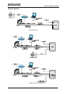
Electrical Connections
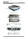
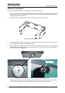
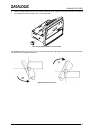
The SC6000 is designed to easily connect to the PWO power supply through two standard accessory cables. All
system cabling is concentrated at the PWO except for some Host connections and the Auxiliary interface for
SC6000 configuration using a laptop PC.
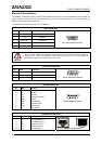
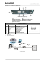
The following connector pinouts are given for reference.
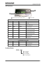
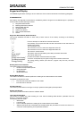
MAIN INTERFACE
Pin RS232 RS485 Full Duplex
2 TX TX485 +
3 RX RX485 +
5 GND_ISO GND_ISO
7 CTS RX485 -
8 RTS TX485 -
5
1
9
6
9-pin D-sub Female Connector
CAUTION
Do not connect GND and GND_ISO to different (external) ground references. GND and
GND_ISO are internally connected through filtering circuitry which can be permanently
damaged if subjected to voltage drops over 0.8 Vdc.
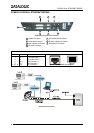
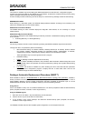
AUXILIARY INTERFACE
Pin Name Function
2 TX Transmit
3 RX Receive
5 GND Ground
5
1
9
6
9-pin D-sub Female Connector
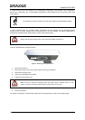
MODEM CONNECTOR
Pin Name Function
1 CD Carrier detect
2 RX Receive
3 TX Transmit
4 DTR Data terminal ready
5 GND Ground
6 DSR Data set ready
7 RTS Request to send
8 CTS Clear to send
9 RI Ring indicator
1
5
6
9
9-pin D-sub Male Connector
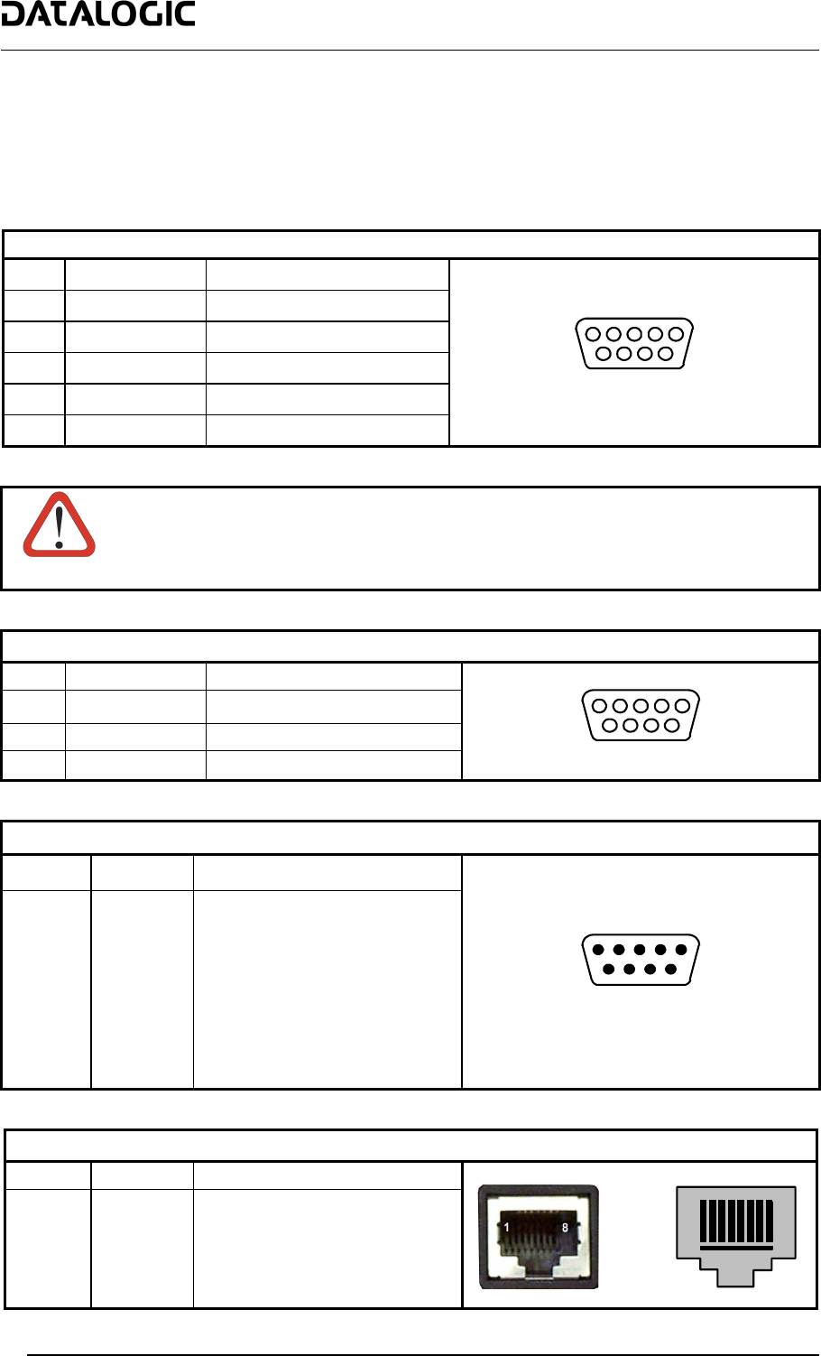
ETHERNET CONNECTOR
Pin Name Function
1 TX + Transmitted data (+)
2 TX - Transmitted data (-)
3 RX + Received data (+)
6 RX - Received data (-)
4, 5, 7, 8 N.C. Not connected
1
8
RJ45 Modular Connector
2