


Back to Contents Page
System Board
Dell™Latitude™131L/
DellVostro™1000ServiceManual
Removing the System Board
Replacing the System Board
The system board BIOS chip contains the Service Tag, which is also visible on a barcode label on the bottom of the computer. The replacement kit for the
system board includes a CD that provides a utility for transferring the Service Tag to the replacement system board.
Removing the System Board
1. Follow the instructions in Before You Begin.
2. Remove the hard drive (see Removing the Hard Drive).
3. Remove the optical drive (see Removing an Optical Drive).
4. Remove the memory module(s) (see Removing the Memory Module(s)).
5. Remove the modem (see Removing the Modem).
6. Remove the hinge cover (see Removing the Hinge Cover).
7. Remove the keyboard (see Removing the Keyboard).
8. Remove the Mini-Card (see Removing a Mini-Card).
9. Remove the display assembly (see Removing the Display Assembly).
10. Remove the palm rest (see Removing the Palm Rest).
11. Remove the fan (see Removing a Fan).
12. Remove the processor thermal-cooling assembly (see Removing the Processor Thermal-Cooling Assembly).
13. Remove the processor (see Removing the Processor Module).
14. Remove the ExpressCard/hard-drive bay assembly (see Removing the ExpressCard/Hard-Drive Bay Assembly).
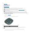
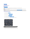
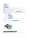
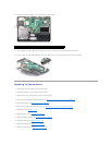
15. Remove the two hex-nut video screws from the back of the computer.
CAUTION: Before you begin the following procedure, follow the safety instructions in the Product Information Guide.
NOTICE: To avoid electrostatic discharge, ground yourself by using a wrist grounding strap or by periodically touching an unpainted metal surface (such
as the back panel) on the computer.
NOTICE: To help prevent damage to the system board, remove the main battery (see Before Working Inside Your Computer) before working inside the
computer.
NOTE: It is not required but is highly recommended that you remove the fan.
1
hex-nut video screws (2)