


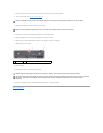


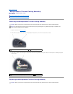


5. Lift the microprocessor module straight up and out of the ZIF-socket.
Replacing the Microprocessor Module
1. Follow the instructions in Before You Begin.
2. Follow the instructions in Removing the Microprocessor Module.
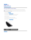
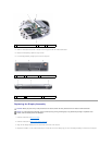
3. Align the pin-1 corner of the new microprocessor module with the pin-1 corner of the ZIF socket, and insert the microprocessor module.
When the microprocessor module is properly seated, all four corners of the module are aligned at the same height. If one or more corners of the module
is higher than the others, the module is not properly seated.
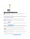
4. To tighten the ZIF-socket cam lock and secure the microprocessor module to the system board, use a small, flat-blade screwdriver and rotate the ZIF-
socket cam screw clockwise until it comes to the cam stop.
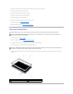
5. Replace the microprocessor thermal-cooling assembly (see Replacing the Microprocessor Thermal-Cooling Assembly).
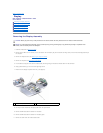
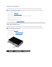
1
microprocessor module
2
ZIF-socket
3
ZIF-socket cam screw
NOTICE: When removing the microprocessor module, pull the module straight up and out of the ZIF-socket. Exercise care not to bend the pins on
the microprocessor module.
NOTE: The microprocessor module and the ZIF-socket illustration shown may not exactly resemble the ones in your system.
CAUTION: Before you perform any of the procedures in this section, follow the safety instructions in the Product Information Guide.
NOTICE: To avoid electrostatic discharge, ground yourself by using a wrist grounding strap or by periodically touching an unpainted metal
surface, such as the back panel on the computer.
NOTE: When installing a new microprocessor module, use the thermal cooling assembly or thermal pad that came with the module, if applicable.
NOTICE: Handle the microprocessor module with care. Hold the microprocessor module by its edges and do not touch the processor die (the small
chip in the center of the module).
NOTICE: Ensure that the cam lock is in the fully open position before seating the microprocessor module. Seating the microprocessor module
properly in the ZIF socket does not require force. A microprocessor module that is not properly seated can result in an intermittent connection or
permanent damage to the microprocessor and ZIF socket.
NOTE: The pin-1 corner of the microprocessor module has a triangle that aligns with the triangle on the pin-1 corner of the ZIF socket.
NOTE: Gently press down on the substrate on which the processor die is mounted to ensure the microprocessor module is properly seated.
NOTICE: To avoid damaging the microprocessor, hold the screwdriver so that it is perpendicular to the microprocessor module when turning the
cam screw.