


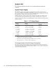
1-14 Dell PowerEdge 2100/180 and 2100/200 Systems Service Manual
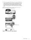
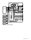
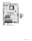
System Board Layout
The subsections that follow provide service-related information about the sys-
tem board components.
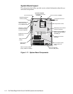
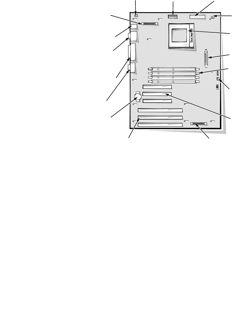
Figure 1-11. System Board Components
keyboard (bottom) and
mouse (top) connec-
tors (KYBD/MOUSE)
video connector
(JVGA)
parallel port connector
(PARALLEL)
serial port 1 (bottom)
and serial port 2 (top)
connectors (SERIAL)
diskette/tape drive interface
connector (FLOPPY)
control-panel connector
(PANEL)
battery socket
(BATTERY)
top of the computer
microprocessor socket
EISA connectors (EISA1
[lower], EISA2, and EISA3)
fan connector (FAN)
power connector (POWER)
3-volt power connector
(POWER3V)
auxiliary fan connector
(AUXFAN)
DIMM connectors (DIMM_A
[lower], DIMM_B, DIMM_C,
and DIMM_D)
PCI connectors (PCI4
[lower], PCI5, and
PCI6)
server management
connector (SRV_MGT)
integrated SCSI port
connector (SCSI)