


Removing and Replacing Parts 4-17
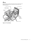
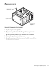
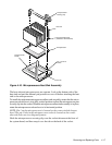
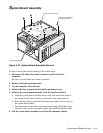
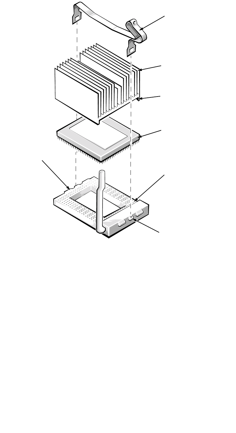
Figure 4-16. Microprocessor/Heat Sink Assembly
The heat sink and microprocessor are separate. Look at the bottom side of the
heat sink and peel the thermal-pad protective cover off before attaching the heat
sink to the microprocessor.
To install the replacement microprocessor/heat sink assembly, ensure that the micro-
processor release lever is in its fully vertical position to allow the microprocessor pins
to easily slip into the socket. When the microprocessor/heat sink assembly is in place,
rotate the microprocessor release lever to its horizontal position.
NOTE: Pin 1 on the microprocessor is located on the corner with the largest
bevel. The pin-1 hole in the microprocessor socket is located on the corner
where the holes are in a diagonal pattern.
Hook the microprocessor securing clip over the socket tab nearest the front of
the system board, and then snap it over the tab on the back of the socket.
heat sink
microprocessor
securing clip
thermal interface pad
(attached to the heat sink)
microprocessor
pin-1 corner of
socket
microprocessor
socket
front tab