


Back to Contents Page
Replacing Memory Module(s)
DellStudio™540ServiceManual
1. Follow the procedures in Before You Begin.
2. Remove the computer cover (see Replacing the Computer Cover).
3. Locate the memory modules on the system board (see System Board Components).
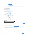
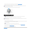
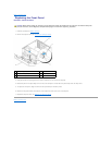
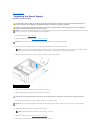
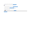
4. Press out the securing clip at each end of the memory module connector.
5. Grasp the module and pull it upwards.
If the module is difficult to remove, gently ease the module back and forth to remove it from the connector.
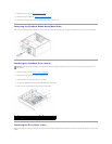
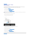
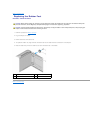
6. Ensure that you install a single memory module in DIMM connector 1, the connector closest to the processor, before you install modules in any other
connector.
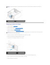
7. Align the notch on the bottom of the module with the with the tab on the memory module connector.
CAUTION: Before working inside your computer, read the safety information that shipped with your computer. For additional safety best
practices information, see the Regulatory Compliance Homepage at www.dell.com/regulatory_compliance.
1
securing clip
2
memory module connector
NOTICE: Do not install ECC memory modules.
NOTICE: If you remove your original memory modules from the computer during a memory upgrade, keep them separate from any new modules that
youmayhave,evenifyoupurchasedthenewmodulesfromDell™.Ifpossible,donotpairanoriginalmemorymodulewithanewmemorymodule.
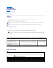
Otherwise, your computer may not start properly. The recommended memory configurations are:
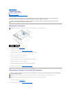
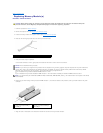
A pair of matched memory modules installed in DIMM connectors 1 and 2.
or
A pair of matched memory modules installed in DIMM connectors 1 and 2 and another matched pair installed in DIMM connectors 3 and 4.
NOTE: If you install mixed pairs of PC2-5300 (DDR2 667-MHz) and PC2-6400 (DDR2 800-MHz) memory, the modules function at the speed of the slowest
module installed.
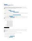
1
Pair A: matched pair of memory
modules in connectors DIMM_1
and DIMM_2
2
Pair B: matched pair of memory
modules in connectors DIMM_3
and DIMM_4