


Back to Contents Page
Replacing the System Board
DellStudio™540ServiceManual
1. Follow the procedures in Before You Begin.
2. Remove the computer cover (see Replacing the Computer Cover).
3. Remove any expansion cards on the system board (see Replacing a PCI/PCI Express Card).
4. Remove the processor and heat sink assembly (see Replacing the Processor Fan and Heat Sink Assembly).
5. Remove the processor (see Replacing the Processor).
6. Remove the memory modules (see Replacing Memory Module(s)), make a note which memory module is removed from each memory socket so that the
memory modules can be installed in the same location after the board is replaced.
7. Disconnect all cables from the system board.
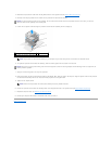
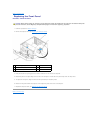
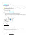
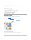
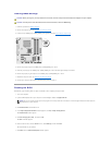
8. Remove the eight screws from the system board.
9. Lift the system board up and out.
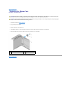
10. Orient the system board by aligning the screw holes on the system board with the screw holes on the chassis.
11. Replace the eight screws to secure the system board to the chassis.
12. Replace the cables that you removed from the system board.
13. Replace the memory modules (see Replacing Memory Module(s)).
14. Replace the processor (see Replacing the Processor).
CAUTION: Before working inside your computer, read the safety information that shipped with your computer. For additional safety best
practices information, see the Regulatory Compliance Homepage at www.dell.com/regulatory_compliance.
NOTICE: Do not perform the following steps unless you are familiar with hardware removal and replacement. Performing these steps incorrectly could
damage your system board. For technical assistance, see the Setup Guide.
CAUTION: The processor heat sink can get very hot during normal operation. Be sure that the heat sink has had sufficient time to cool before you
touch it.
NOTICE: Carefully note the routing and location of each cable before you disconnect it, so that you are sure to re-route cables correctly. An incorrectly
routed or a disconnected cable could lead to computer problems.
1
screws (8)
2
system board
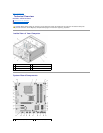
NOTICE: If you are replacing the system board, visually compare the replacement system board to the existing system board to make sure that you
have the correct part.
NOTE: Some components and connectors on replacement system boards may be in different locations compared to the existing connectors on the
system board.
NOTE: Jumper settings on replacement system boards are preset at the factory.