


24
APRIL 2008
MSTP INTEROPERABILITY OF THE DELL™ POWERCONNECT™ 6200 SERIES SWITCHES
WITH CISCO IOS AND CISCO CATOS-BASED SWITCHES
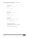
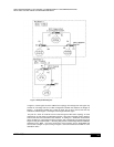
Figure 7: Multiple MSTP Regions
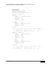
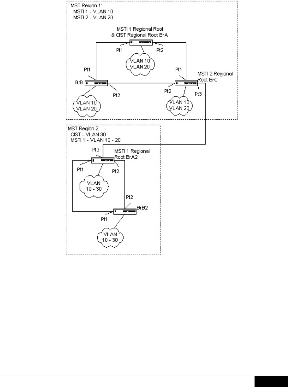
In Figure 8, a third region has been added to the topology. Even though this new region only
consists of one bridge and has an MST Configuration Identifier that matches the bridges in
Region 1, it will still be isolated into a region by itself. This is due to the fact that the only
connection between Region 1 and Region 3 is through a different region.
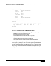
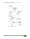
The path of a frame for VLAN 20 can be traced through the MST active topology. A frame
originating on an end station on bridge BrA in Region 1 will traverse the MSTI 2 active topology
since its VID has been allocated to that instance. In looking for a destination match with a
device in Region 3, it will pass through the boundary port in bridge BrC and continue through
Region 2 using the instance MSTI 1. Assuming that port Pt2 on both bridge BrA2 and BrB2 are
forwarding for the MSTI 1, the frame would arrive at the boundary port on bridge BrB2 and
then be sent to Region 3. Upon arriving in Region 3, the frame would traverse MSTI 2 to the
destination device.