


8
APRIL 2008
MSTP INTEROPERABILITY OF THE DELL™ POWERCONNECT™ 6200 SERIES SWITCHES
WITH CISCO IOS AND CISCO CATOS-BASED SWITCHES
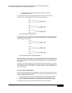
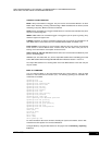
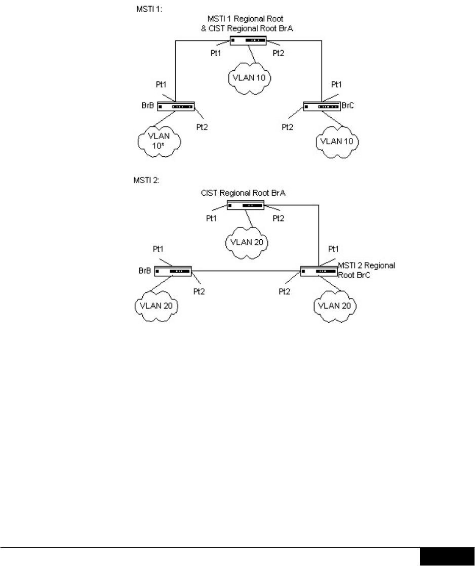
In this simple case, VLAN 10 could be associated with MSTI 1 with an active topology similar
to Figure 5, and VLAN 20 could be associated with MSTI 2 where port Pt1 on both bridge BrA
and BrB begin discarding and all others begin forwarding. This simple modification creates an
active topology with a better distribution of network traffic and an increase in available
bandwidth. The logical representation of the MSTP environment for these 3 bridges is shown in
Figure 6.
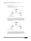
Figure 6: Logical MSTP Environment
In order for MSTP to correctly establish the different MSTIs that Figure 6 shows, some
additional changes are required. For example, the configuration would have to be the same on
each and every bridge. That means that bridge BrB would have to add VLAN 10 to its list of
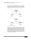
supported VLANs (shown in Figure 6 with an “*”). This is necessary with MSTP to allow the
formation of regions made up of all bridges that exchange the same MST Configuration
Identifier. It is only within these MST regions that multiple instances can exist. It will also allow
the election of Regional Root Bridges for each instance. One CIST Regional Root for the CIST
and an MSTI Regional Root Bridge per instance will enable the possibility of alternate paths
through each Region. Above bridge BrA is elected as both the MSTI 1 Regional Root and the
CIST Regional Root Bridge, and after adjusting the Bridge Priority on bridge BrC in MSTI 2, it
would be elected as the MSTI 2 Regional Root.