


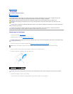

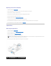


4. Connect the chassis fan cable to the system board connector, FAN_SYS1 (see System Board Components).
5. Replace the computer cover (see Replacing the Computer Cover).
Processor Fan and Heat-Sink Assembly
Removing the Processor Fan and Heat-Sink Assembly
1. Follow the instructions in Before You Begin.
2. Remove the computer cover (see Removing the Computer Cover).
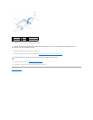
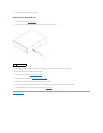
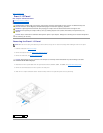
3. Disconnect the processor fan cable from the system board connector, FAN_CPU (see System Board Components).
4. Using a flat-blade screwdriver, loosen the four captive screws that secure the processor fan and heat-sink assembly to the system board.
5. Lift the processor fan and heat-sink assembly out of the computer.
Replacing the Processor Fan and Heat-Sink Assembly
1. Follow the instructions in Before You Begin
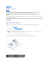
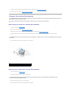
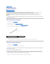
2. Clean the thermal grease from the bottom of the heat-sink.
3. Apply new thermal grease to the top of the processor.
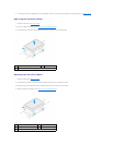
4. Place the processor fan and heat-sink assembly over the processor.
WARNING: Despite having a plastic shield, the processor fan and heat-sink assembly may be very hot during normal operation. Ensure that it has
had sufficient time to cool before you touch it.
CAUTION: The processor fan and heat-sink assembly is a single unit. Do not try to remove the fan separately.
CAUTION: When you remove the processor fan and heat-sink assembly, lay it upside down or on its side to avoid damaging the heat-sink thermal
interface.
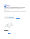
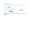
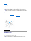
1
processor fan cable
2
processor fan and heat-sink assembly
3
captive screws (4)
CAUTION: Ensure that you apply new thermal grease. New thermal grease is critical for ensuring adequate thermal bonding, which is a
requirement for optimal processor operation.