


4 Replacing the System and Backplane Board Assemblies
www.dell.com | support.dell.com
17
Loosen the two thumbscrews securing the riser board and disconnect it from the system
board card-edge connector. See "Removing the Riser Board" in your
Installation and
Troubleshooting Guide.
18
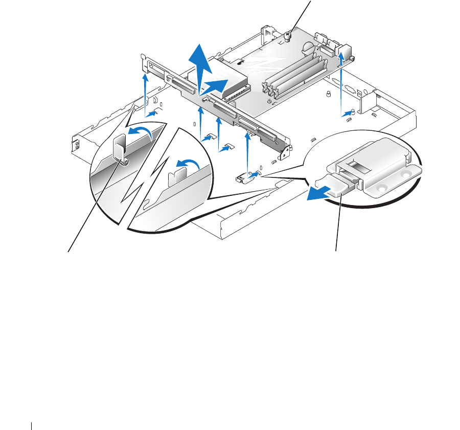
Slide the backplane securing latch forward to the open position to allow the system
board/backplane board to move to the forward (unlatched) position.
19
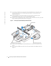
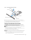
Slide the system board/backplane board assembly forward, toward the front of the system and
lift the assembly up and out of the chassis. See Figure 1-1.
Figure 1-1. Removing the System Board/Backplane Board Assembly
20
Lay the system board/backplane board assembly down on a smooth, nonconductive work
surface.
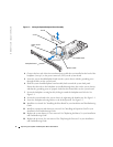
21
Remove the three Phillip screws that secure the system board to the backplane board. See
Figure 1-2.
thumbscrew
backplane release latches (2)
backplane securing latch