6 Replacing the System and Backplane Board Assemblies
www.dell.com | support.dell.com
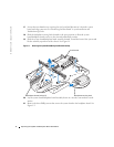
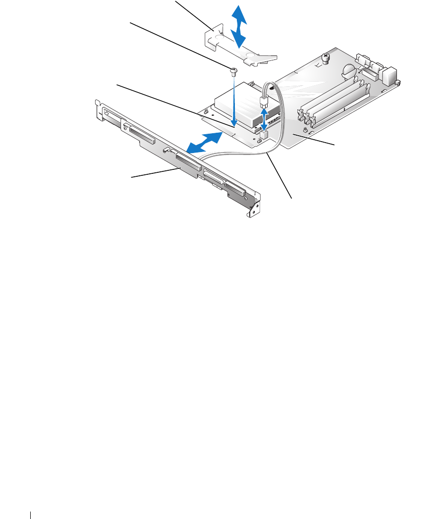
Figure 1-3. Joining the System/Backplane Board Assembly
4
Connect the free end of the four-conductor power cable that you installed on the back of the
backplane (in step 1) to the power connector (CN2) on the system board.
5
Lower the system board/backplane board into the system chassis with the grounding posts
through the holes on the system board.
6
Slide the system board/backplane board assembly back towards the system back panel.
Ensure that the tabs on the backplane are installed through their slots on the system chassis,
and that the grounding posts are properly locked in their slotted holes on the system board.
7
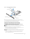
Secure the backplane securing latch by sliding it toward the backplane until it locks. See
Figure 1-1.
8
Secure the system board to the system chassis by tightening the thumbscrew. See Figure 1-1.
9
Lower the backplane releasing latches to the locked position. See Figure 1-2.
10
Install the riser board. See "Installing the Riser Board" in your
Installation and Troubleshooting
Guide
.
11
Install any expansion cards that were removed. See "Installing an Expansion Card" in your
Installation and Troubleshooting Guide
.
12
Replace the system battery, if it was removed. See "Replacing the Battery" in your
Installation
and Troubleshooting Guide
.
13
Replace the processor, if it was removed. See "Replacing the Processor" in your
Installation
and Troubleshooting Guide
.
system board
screw
shroud
backplane board
power cable
center screw
hole


