


Back to Contents Page
Microprocessor
DellPrecision™Workstation650andDellPrecisionWorkstation450ServiceManual
Installation Guidelines
Installing the Microprocessor
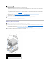
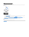
Removing the Microprocessor
Installation Guidelines
l Your computer is designed for dual-processor operations. The heat sinks (CPU_0 and CPU_1) are keyed to fit their specific connector.
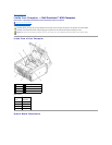
l For single-processor operations, the processor must be installed in socket CPU_0. The VRM for the single processor is already installed and cannot be
removed. Processor socket 1 and VRM connector 1 must be empty. To locate these components, see the system board components illustration (for the
Dell Precision 450 computer, see "System Board Components" or for the Dell Precision 650 computer, see "System Board Components") or the system
board label inside your computer.
l For dual-processor operations, both processor sockets and the VRM connector must be populated. To locate the VRM connector, see the system board
components illustration (for the Dell Precision 450 computer, see "System Board Components" or for the Dell Precision 650 computer, see "System Board
Components")or the system board label inside your computer.
l For dual-processor operations, the two processors and the VRMs must be identical. If the processors do not match, you receive a system message. If
the processors voltage don't match or the VRM is not properly installed, the diagnostic lights indicate an error..
l If you are upgrading your microprocessor, keep your original microprocessor heat sink and securing clips for future troubleshooting.
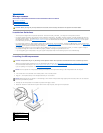
Installing the Microprocessor
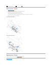
1. Remove the microprocessor airflow shroud (for the Dell Precision 650 computer, see "Microprocessor Airflow Shroud — DellPrecision™650Computer" or
for the Dell Precision 450 computer, see "Microprocessor Airflow Shroud — DellPrecision™450Computer").
If you are replacing a microprocessor, see "Removing the Microprocessor."
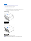
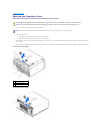
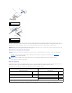
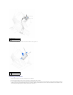
2. If the release lever is not extended to the release position, move it to that position.
3. Align pin-1 (the imprinted corner) of the microprocessor and pin-1 of the socket.
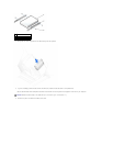
4. Carefully set the microprocessor in the socket and press it down lightly to seat it.
5. Rotate the release lever back toward the system board until it snaps into place, securing the microprocessor.
CAUTION: Before you begin any of the procedures in this section, follow the safety instructions in the System Information Guide.
CAUTION: The processor can get very hot during normal operation. Ensure that the processor has had sufficient time to cool before you touch it.
NOTICE: You must position the microprocessor correctly in the socket to avoid permanent damage to the microprocessor and the computer.
NOTICE: Microprocessor pins are delicate. To avoid damage, ensure that the microprocessor aligns properly with the socket, and do not use excessive
force when you install the processor.
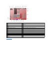
1
microprocessor pin-1
indicator
2
release lever
3
microprocessor
4
microprocessor socket