15
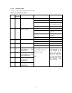
2.4.1.3 Indicator LEDs
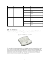
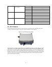
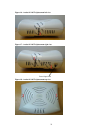
There is an array of LEDs which operate as follows:
Table 5- AP-175 Indicator LEDs
Label
LED
Position
Function
Action
Status
PWR
D11
AP power / system status
Off
No power to AP
Red
System Alarm
Flashing - Green
Power did not connect
well or equipment failure
On - Green
Device ready
ENET0
D15
Ethernet Network Link
Status / Activity
Off
Ethernet link unavailable
On - Yellow
10/100Mbs Ethernet link
negotiated
On - Green
1000Mbs Ethernet link
negotiated
Flashing
Ethernet link activity
WLAN0
D6
Radio0 Status
Off
Radio0 disabled
On - Orange
Radio0 enabled
WLAN1
D1
Radio1 Status
Off
Radio1 disabled
On - Blue
Radio1 enabled
SS1
D7/D2
Signal Strength
(Radio0/Radio1) least
significant bit
On - Orange/Blue
(For Radio0: Orange and
For Radio1: Blue)
Off
SS1 to SS4 LEDs turn
on/off depending on the
signal strength of the
current radio neighbors.
Stronger the signal, more
LEDs get lit starting with
SS1 (least signal strength
indicator) all the way to
SS4 (highest signal
strength indicator).
SS2
D8/D3
Signal Strength
(Radio0/Radio1) second
most significant bit
SS3
D9/D4
Signal Strength
(Radio0/Radio1) least
significant bit
SS4
D10/D5
Signal Strength
(Radio0/Radio1) most
significant bit


