


Back to Contents Page
System Board
Dell™Latitude™D430
Removing the System Board
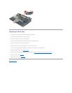
Replacing the System Board
Removing the System Board
The system board's BIOS chip contains the Service Tag, which is also visible on a barcode label on the bottom of the computer. The replacement kit for the
system board includes a CD that provides a utility for transferring the Service Tag to the replacement system board.
1. Follow the instructions in "BeforeYouBegin"onpage7.
2. Remove any installed PC Cards from the PC Card slot.
3. Remove any installed memory modules or Mini PCI cards (see Memory and Mini-Cards).
4. Remove the hard drive (see Hard Drive).
5. Remove the hinge cover (see Hinge Cover).
6. Remove the keyboard (see Keyboard).
7. Remove the internal card with Bluetooth®wireless technology (see Internal Card With Bluetooth®Wireless Technology).
8. Remove the display assembly (see Display Assembly).
9. Remove the palm rest (see Palm Rest).
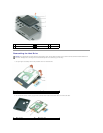
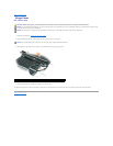
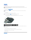
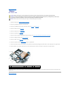
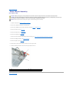
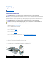
10. Disconnect the power button connector from the system board.
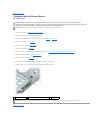
11. Disconnect the suspend-switch sensor board connector from the system board.
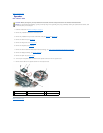
12. Remove the remaining two M2.5 x 5-mm screws that secure the system board to the computer base.
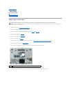
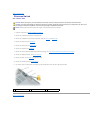
13. Lift the system board at an angle toward the side of the computer and out of the computer base.
CAUTION: Before you begin any of the procedures in this section, follow the safety instructions in the Product Information Guide.
NOTICE: To avoid electrostatic discharge, ground yourself by using a wrist grounding strap or by periodically touching an unpainted metal surface (such
as the back panel) on the computer.
CAUTION: Before you begin any of the procedures in this section, follow the safety instructions in the Product Information Guide.
CAUTION: To prevent static damage to components inside your computer, discharge static electricity from your body before you touch any of
your computer's electronic components. You can do so by touching an unpainted metal surface.
NOTICE: Handle components and cards by their edges, and avoid touching pins and contacts.
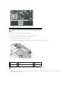
1
computer base
2
M2.5 x 5-mm screws (2)
3
system board assembly
4
power button connector
5
suspend-switch sensor board