


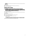
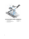
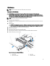
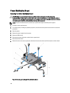
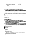

1. screws (2)
2. power supply cables to the system board (3)
3. power supply cable to the hard-drive
backplane
4. standoffs (2)
5. power distribution board
6. fan cable connector
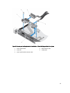
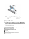
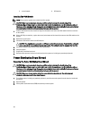
Installing The Power Distribution Board
CAUTION: Many repairs may only be done by a certified service technician. You should only perform
troubleshooting and simple repairs as authorized in your product documentation, or as directed by the online or
telephone service and support team. Damage due to servicing that is not authorized by Dell is not covered by your
warranty. Read and follow the safety instructions that came with the product.
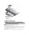
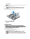
1. Align the power distribution board with the standoffs on the chassis.
2. Install the two screws that secure the power distribution board to the chassis.
3. Connect the power distribution cables to the system board and fan cable connector to the power distribution board.
4. Install the PDB shroud.
5. Close the system.
6. Reconnect the system to its electrical outlet and turn the system on, including any attached peripherals.
System Board
Removing The System Board
CAUTION: Many repairs may only be done by a certified service technician. You should only perform
troubleshooting and simple repairs as authorized in your product documentation, or as directed by the online or
telephone service and support team. Damage due to servicing that is not authorized by Dell is not covered by your
warranty. Read and follow the safety instructions that came with the product.
CAUTION: If you are using the Trusted Program Module (TPM) with an encryption key, you may be prompted to
create a recovery key during program or System Setup. Be sure to create and safely store this recovery key. If you
replace this system board, you must supply the recovery key when you restart your system or program before you
can access the encrypted data on your hard drives.
1. Turn off the system, including any attached peripherals, and disconnect the system from the electrical outlet.
2. If installed, remove the front bezel.
3. Open the system.
4. Remove the following:
a) cooling shroud
b) PDB shroud
c) memory modules
d) expansion cards and the expansion-card risers
e) integrated storage controller card
WARNING: The heat sink and processor are hot to the touch for some time after the system has been
powered down. Allow the heat sink and processor to cool before handling them.
f) heat sink/heat-sink blank and processor/processor blank
g) integrated storage controller card
101