


Drive-Status
Indicator Pattern
(RAID Only)
Condition
Blinks green three
seconds, amber three
seconds, and off six
seconds
Rebuild aborted
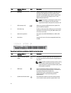
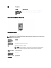
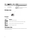
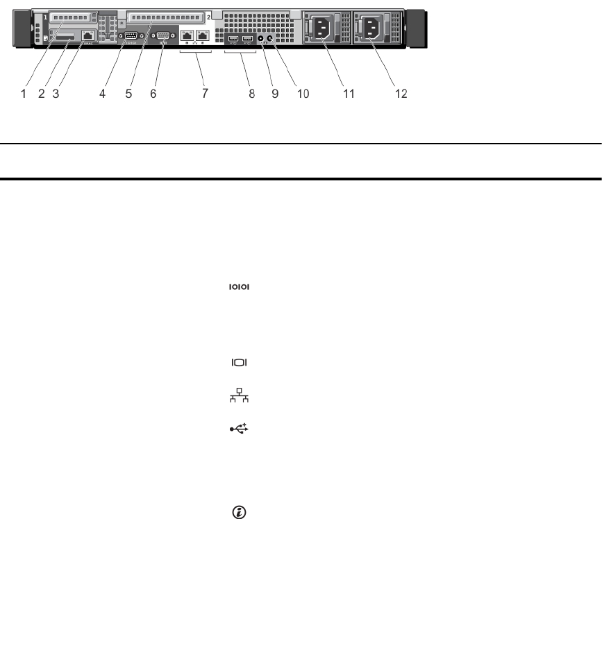
Back-Panel Features And Indicators
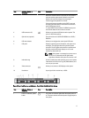
Figure 6. Back-Panel Features and Indicators
Item Indicator, Button, or
Connector
Icon Description
1 PCIe expansion card slot 1 Allows you to connect one low-profile PCI Express
expansion card.
2 vFlash card slot Allows you to connect the vFlash card.
3 iDRAC port (optional) Dedicated management port on the iDRAC Ports card.
4 Serial connector Allows you to connect a serial device to the system.
5 PCIe expansion card slot 2 Allows you to connect a full-height PCI Express expansion
card.
6 Video connector Allows you to connect a VGA display to the system.
7 Ethernet connectors (2) Integrated 10/100/1000 Mbps NIC connector.
8 USB connectors (2) Allows you to connect USB devices to the system. The
ports are USB 2.0-compliant.
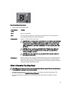
9 System identification
connector
Connects the optional system status indicator assembly
through the optional cable management arm.
10 System identification button The identification buttons on the front and back panels
can be used to locate a particular system within a rack.
When one of these buttons is pressed, the system status
indicator on the back flashes until one of the buttons is
pressed again.
Press to toggle the system ID on and off. If the system
stops responding during POST, press and hold the system
ID button for more than five seconds to enter BIOS
progress mode.
17