


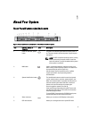

Item Indicator, Button, or
Connector
Icon Description
NOTE: On ACPI-compliant operating systems, turning
off the system using the power button causes the
system to perform a graceful shutdown before power
to the system is turned off.
2 NMI button
Used to troubleshoot software and device driver errors
when running certain operating systems. This button can
be pressed using the end of a paper clip.
Use this button only if directed to do so by qualified
support personnel or by the operating system's
documentation.
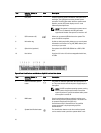
3 System identification button The identification buttons on the front and back panels
can be used to locate a particular system within a rack.
When one of these buttons is pressed, the system status
indicator on the back flashes until one of the buttons is
pressed again.
Press to toggle the system ID on and off. If the system
stops responding during POST, press and hold the system
ID button for more than five seconds to enter BIOS
progress mode.
To reset the iDRAC (if not disabled in F2 iDRAC setup)
press and hold the button for more than 15 seconds.
4 Video connector Allows you to connect a VGA display to the system.
5 Diagnostic indicators The diagnostic indicators light up to display error status.
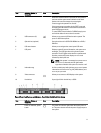
6 USB connectors (2) Allows you to connect USB devices to the system. The
ports are USB 2.0-compliant.
7 Information tag A slide-out label panel which allows you to record system
information such as Service Tag, NIC, MAC address, and
so on as per your need.
8 Optical drive (optional) One optional slim SATA DVD-ROM drive or DVD+/-RW
drive.
9 Hard drives Up to four 3.5 inch cabled hard drives.
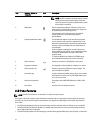
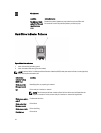
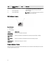
LCD Panel Features
NOTE: The LCD Panel feature is not available in a cabled hard-drive system.
The system's LCD panel provides system information and status and error messages to indicate when the system is
operating correctly or when the system needs attention. See System Error Messages for information about specific
error codes.
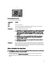
• The LCD backlight lights blue during normal operating conditions and lights amber to indicate an error condition.
• The LCD backlight is off when the system is in standby mode and can be turned on by pressing either the Select,
Left, or Right button on the LCD panel.
• The LCD backlight remains off if LCD messaging is turned off through the iDRAC utility, the LCD panel, or other tools.
12