


26
|
Installation
CAUTION: To ensure the UPS stops supplying power to the load during any mode of operation, the input
power must be disconnected from the UPS when the emergency power-off function is activated.
NOTE: For Europe, the emergency switch requirements are detailed in Harmonized document HD-384-48 S1,
“Electrical Installation of the Buildings, Part 4: Protection for Safety, Chapter 46: Isolation and Switching.”
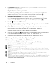
REPO Connections
Wire Function Terminal Wire Size Rating Suggested Wire Size
REPO
L1
4–0.32 mm
2
(12–22 AWG) 0.82 mm
2
(18 AWG)
L2
NOTE: The pins must be open to keep the UPS running. If the UPS shuts down because the REPO connector
pins are shorted, restart the UPS by re-opening the REPO connector pins and turning on the UPS manually.
Maximum resistance in the shorted loop is 10 ohm.
NOTE: Always test the REPO function before applying your critical load to avoid accidental load loss.
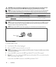
Remove Jumper if
installed
Figure 18. REPO Connector
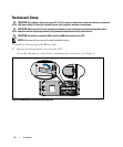
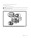
To install the REPO switch:
1 Verify that the UPS is off and unplugged.
2 Remove the REPO connector from the accessory kit.
NOTE:
Verify that there is no jumper installed in the REPO connector. If a jumper is installed, remove it before
connecting to the REPO port.
3 Connect the REPO connector to the REPO port labeled “IN” on the UPS rear panel.
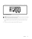
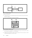
4 Optional. If you are daisy-chaining the REPO function with another UPS, you can shut down the
entire system using a single switch.
Connect the second REPO connector to the REPO port labeled “OUT.”