


29
Installation
|
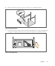
5 Insert the conduit through the wiring access entry and attach the conduit fitting to the panel.
Strip 0.5” (1.5 cm) of insulation from the end of each incoming wire.
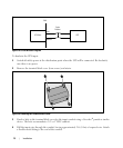
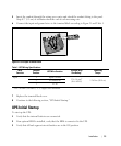
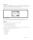
6 Connect the input and ground wires to the terminal block according to Figure 21 and Table 1.
Figure 21. UPS Input Terminal Block
Table 1. UPS Wiring Specifications
Wire
Function
Terminal
Position
UPS Wire Function
Terminal Wire
Size Rating*
Tightening
Torque
Input
1 Input Ground
5.26–16 mm
2
(10–6 AWG)
2.26 Nm (20 lb in)
2 L2/Neutral In
3 L1 In
* Use 5.26 mm
2
(10 AWG) 75_C copper wire minimum.
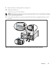
7 Replace the terminal block cover.
8 Continue to the following section, “UPS Initial Startup.”
UPS Initial Startup
To start up the UPS:
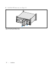
1 Verify that the internal batteries are connected.
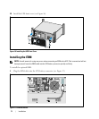
2 If an optional EBM is installed, verify that the EBM is connected to the UPS.
3 Verify that all load segment circuit breakers are in the ON position.