


6
CONNECTIONS OF THE MS700I/MS720I
WITH
“MX” TO THE HOST DEVICE
To avoid potential problems, do not power up the scanner until the
communication cable is secured to the host.
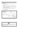
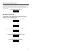
1. Turn off the host system.
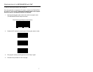
2. Connect the 25-pin D-type connector on the MS700i/MS720i scanner’s
head cable to the communication cable. Connect the other end of the
communication cable to the host device. If the scanner will not receive
power from a transformer, skip to Step 5.
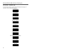
3. If the scanner will receive power from an external power source, check
the AC input requirements of the transformer to make sure the voltage
matches the AC outlet. The socket-outlet should be near the equipment
and easily accessible.
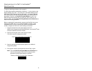
4. Plug the transformer into the side of the female D-type connector
located on the communication cable. Plug the transformer into the AC
outlet to supply power to the scanner.
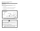
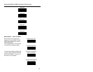
5. Power up the host system.
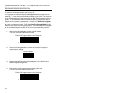
6. Attach the “MX” to the MS700i/MS720i scanner via the LSO cable that
terminates to a 10-pin modular connector.
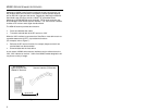
Note: When the MS700i/MS720i scanner first receives power, the
LEDs will flash and then the scanner will beep once. After the
scanner performs this startup sequence, the green LED will remain
on for a specified time showing that the laser is on.
Refer to the MS700i and MS720i Laser Bar Code Projection
Scanner Installation and User’s Guide for information on how to
operate the scanner.
To maintain compliance with applicable standards, all circuits connected
to the unit must meet the requirements for SELV (Safety Extra Low
Voltage) according to EN 60950.
The following statement is applicable if the scanner will receive power
from a host device such as a computer system.
Caution: To maintain compliance with standards CSA C22.2 No. 950/UL
1950 and norm EN60950, the power source must meet
applicable performance requirements for a limited power
source.