


11 Using MLAG in Dell Networks
.
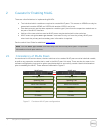
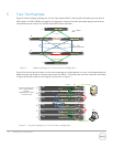
Note: Interfaces used to connect each peer to the partner switch LAG do not need to match on each
peer. For instance, in the example above, one partner LAG interface connects to 1/0/47 on the primary
peer while the other interface connects to 1/0/11 on the secondary peer.
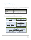
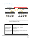
2. Connect all cables as shown in Figure 4.
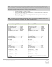
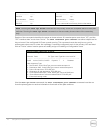
3. Run the show vpc brief command on either of the two MLAG peers to see which
peer is the primary MLAG peer.
4. Run the show vpc brief command again from the primary switch to display all
information for both peers.
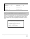
Note: The partner switches must be configured with MLAGs and connected to the MLAG peers, or the
“Number of VPCs operational” in the show vpc brief command shows 0.
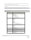
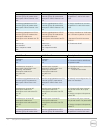
Primary MLAG Peer
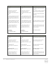
Secondary MLAG Peer
show vpc brief
VPC admin status............................... Enabled
Keep-alive admin status................... Enabled
VPC operational status..................... Enabled
Self role................................................ Primary
Peer role.............................................. Secondary
Peer detection admin status........... Disabled
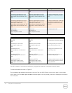
Peer-Link details
-----------------
Interface.................................................. Po1
Peer-link admin status......................... Enabled
Peer-link STP admin status................. Disabled
Configured VLANs................................. 1,30
Egress tagged VLANs............................ 30
VPC Details
-----------
Number of VPCs configured...................... 2
Number of VPCs operational..................... 2
VPC id# 30
-----------
Interface.................................................... Po30
Configured VLANs.................................. 1,30
VPC interface state................................. Active
Local Members Status
----------------- ------
Gi1/0/47 Up
Peer Members Status
---------------- ------
Gi1/0/11 Up
VPC id# 40
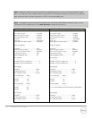
show vpc brief
VPC admin status................................... Enabled
Keep-alive admin status....................... Enabled
VPC operational status......................... Enabled
Self role.................................................. Secondary
Peer role................................................ Primary
Peer detection admin status............... Disabled
Peer-Link details
-----------------
Interface.................................................. Po1
Peer-link admin status......................... Enabled
Peer-link STP admin status................. Disabled
Configured VLANs................................. 1,30
Egress tagged VLANs............................ 30
VPC Details
-----------
Number of VPCs configured...................... 2
Number of VPCs operational..................... 2
VPC id# 30
-----------
Interface.................................................... Po30
Configured VLANs.................................. 1,30
VPC interface state................................. Active
Local Members Status
----------------- ------
Gi1/0/11 Up
Peer Members Status
---------------- ------
< * run command from Primary for this information >
VPC id# 40