20 Using MLAG in Dell Networks
.
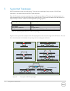
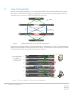
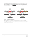
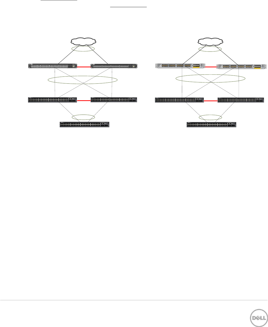
In Figure 9 below, the first topology shows MLAG peers on one layer and Dell VLT peers on the second
layer, with a full-mesh LAG. The second topology shows MLAG peers on one layer and Cisco vPC (or
Cisco VSS) on the second layer, also with a full-mesh LAG. Neither full mesh configuration shown in these
scenarios is compatible.
LAG
N3048
N3048
Peer-
Link
MLAG
VLTi
S4810
S4810
QSFP+
MASTER
SYS
FAN
PSU
RS-232
ETHERNET
LNK ACT
4644424038363432302826242220181614121086420 48 56
52 60
SFP+
Force10 S4810P
QSFP+
MASTER
SYS
FAN
PSU
RS-232
ETHERNET
LNK ACT
4644424038363432302826242220181614121086420 48 56
52 60
SFP+
Force10 S4810P
LAG
N3048
N3048
Peer-
Link
MLAG
vPC
Cisco
Cisco
LAG
CISCO NEXUS 2232TP 10GE FABRIC EXTENDER
STAT
2526 27 28 29 30 31321718 19 20 21 22 2324910 11 12 13 14 15 1612 34 56 78
ID
12 34 56 78
CISCO NEXUS 2232TP 10GE FABRIC EXTENDER
STAT
2526 27 28 29 30 31321718 19 20 21 22 2324910 11 12 13 14 15 1612 34 56 78
ID
12 34 56 78
LAG
X
X
Unsupported LAG configurations Figure 9
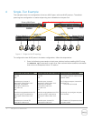
When using MLAG in a full-mesh LAG, no other peer technology can be used. To use another peer
technology on a second layer, LAGs must be configured only on the MLAG peer switches (like in Figure 7).
or only on the other peer switches that are using Dell VLTi or Cisco vPC. Either side works as long as both
LAGs are created on the same peer set.


