11
8.2.6 Voltage Tracking
The DNM/DNL family was designed for applications that have output voltage tracking
requirements during power-up and power-down. The devices have a TRACK pin to implement
three types of tracking method: sequential, ratio-metric and simultaneous. TRACK simplifies
the task of supply voltage tracking in a power system by enabling modules to track each
other, or any external voltage, during power-up and power-down.
By connecting multiple modules together, customers can get multiple modules to track their
output voltages to the voltage applied on the TRACK pin.
Detailed Description
Sequential Implementation
Sequential start-up is implemented by connecting the power good signal (PWRGD pin) of PS1
to the TRACK pin of PS2 with a resistor–capacitor (RC) circuit. The power up and down that
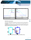
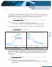
waveforms in Figures 4 and 5. In Figure 4, the 5V PS1 supply ramps up first. When supply
reaches its final 5V steady state value, the open collector output of the PWRGD pin releases
to the TRACK pin and the PS2 output voltage rises at the rate of the RC time constant. In
Figure 5, the PWRGD pin pull low by PS1 ENABLE off or the PS1 output voltage is below 90%
of the desired regulated voltage. The TRACK pin is pulled low and the PS2 power down.
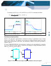
Figure 3 shows the circuit diagram of sequential start-up when Vo
PS2
tracks the PWRGD of
PS1.
R
TRACK
Vo
PS1
PS2
Vo
PS2
PS1
Vin
Vin
PWRGD
ENABLE
ENABLE
C
Figure 3. PS1 and PS2 track output voltage Sequential start-up


