


4
6.0 Tests Performed
The following tests are performed at room temperature (+25 ℃).
6.1 Input Characteristics
Input Voltage Range.
Under-Voltage Lockout.
No Load Input Current.
6.2 Output Characteristics
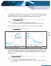
Line Regulation.
Load Regulation.
Output Regulation.
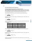
Output Voltage Set-point Programming
Output Voltage Margining
Output Voltage Tracking
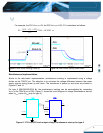
6.3 Dynamic Characteristics
Maximum Output Voltage Deviation (due to step change in load).
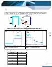
Turn on Response time.
6.4 Thermal Characteristic
Efficiency
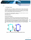
7.0 Test Set-Up
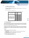
7.1 Initial Set-Up
1) Examine the part number of the power module to determine that the correct module is
being evaluated. Note: DNM04S0A0S10P A would denote the SMT package, while
DNM04S0A0R10P A would denote the SIP package. This Evaluation Board is for use with
SMT package.
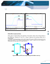
2) Set the multi-meter DVM1 to the DC current 20A range. Set multi-meters DVM2 and
DVM3 to DC voltage, auto ranging.
3) Electronic Load
Turn on the Electronic Load at CR mode (or resistive load) and adjust the current level.
The maximum rated output current is 10A for the model DNM series and 16A for the DNL
series. Ensure the output load does not exceed the recommended maximum current.
4) SW1 is used for on/off Transient function test. Turn SW1 to the OFF position if this function
is not being used. Turn SW1 to the ON position if the Transient function test is required.