12
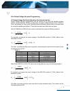
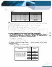
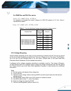
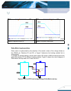
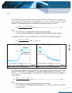
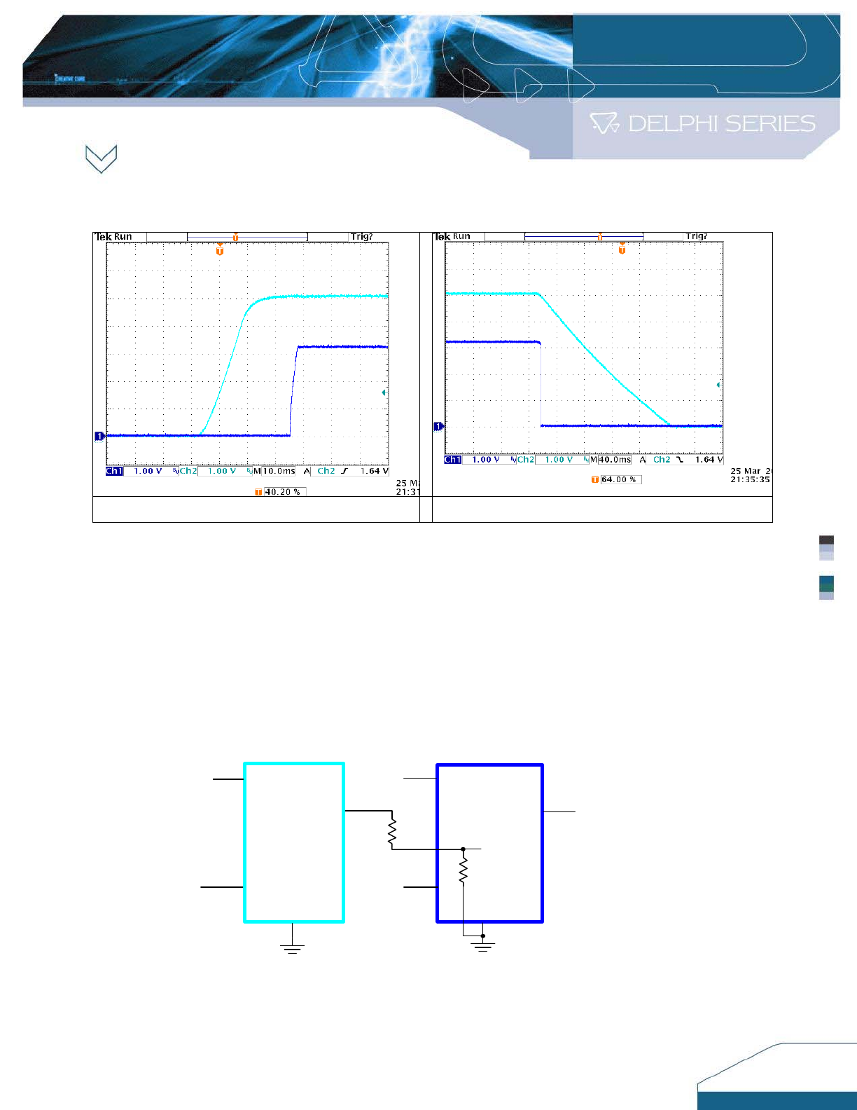
Figure 4: Sequential Power up Figure 5: Sequential Power down
Ratio-Metric Implementation
Ratio–metric is implemented by the selection of the resistor values of the voltage divider on
the TR
A
CK pin. Resistors R1 and R2, in Figure 6 determine the tracking method that is
implemented.
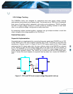
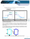
To simplify the tracking design, set the initial value of R2 equal to 20KΩ at internal circuit and
adjust the resistor R1 for different tracking method. Figure 6 shows the circuit diagram of
Ratio-Metric start-up when Vo
PS2
tracks the Vo
PS1
.
R1
R2
TRACK
Vo
PS1
PS2
Vo
PS2
PS1
Vin
Vin
ENABLE
ENABLE
To Tracking
circuit
20K
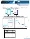
Figure 6. PS1 and PS2 track output voltage Ratio-Metric start-up
PS1
PS2
PS1
PS2


