


3
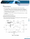
4.1 Connect one lead from the “+” lead of the DC source (See Item 3.1) to the “20A” terminal of the
first multi-meter DVM1 (See Item 3.3). Then connect one lead from the “Common” of the DVM1
to the “Vin” pin of the Evaluation Board. DVM1 is used to measure the input current.
4.2 Connect one wire from the “-” lead of the DC source (See Item 3.1) to the “GND“ pin of the
Evaluation Board. Note: Use stranded leads at least equivalent to 14 AWG for all connections
in sections 4.1 and 4.2. The leads should be twisted to reduce noise coupling.
4.3 Connect the plus “+” and minus “-“ connection leads from a second multi-meter (See Item 3.3)
to the “SVin” and “SGND” pins on the Evaluation Board. This multi-meter is designated DVM2.
DVM2 is used to measure the input voltage.
4.4 Connect the plus “+” and minus “-“ connection leads from the third multi-meter (See Item 3.3) to
the “SVOUT” and “SGND” Pin on the Evaluation Board. The multi-meter is designated DVM3.
DVM3 is used to measure the output voltage.
4.5 Connect a BNC cable (length less than 20 inches/500mm) from BNC1 of the Evaluation Board
to Channel 1 of the oscilloscope (See Item 3.2). This cable is used to measure the input
voltage (between SVIN and SGND).
4.6 Connect a BNC cable (length less than 20 inches/500mm) from BNC2 of the Evaluation Board
to Channel 2 of the oscilloscope (See Item 3.2). This cable is used to measure the output
voltage (between SVOUT and SGND).
4.7 Connect the positive and negative power leads of the electronic load (ensuring correct polarity),
or an appropriate resistive load to the Evaluation Board output terminal pin (“Vout” for positive
power lead and “SGND” for the negative power lead).
4.8 Connect one lead from the “+” lead of the DC source (See Item 3.5) to the “12Vcc” on the
Evaluation Board. Then connect one lead from the “-” of the DC source (See Item 3.5) to the
“12VGND” on the Evaluation Board.
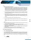
5.0 Thermal Management of the Converter
It is imperative that sufficient airflow needs to be provided to the converter at all times during all
portions of testing. Please refer to the applicable data sheet for the proper cooling and derating
necessary conditions to obtain accurate results when testing the converter.