


Chapter 12 Application Examples |ASDA-AB Series
Revision March 2008, Doc. Name: 2007PDD23000011 12-15
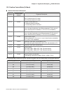
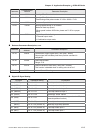
Parameter
Communication
Address
Parameter Description
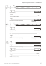
P1-50 0132H Homing Offset Rotation Number
P1-51 0133H Homing Offset Pulse Number
Total homing offset pulse number =P1-50 x 10000 + P1-51
P1-55 0137H Maximum Speed Limit
P2-36 0224H Moving Speed Setting of 1st Position
Maximum feed step speed
(When speed is above 3000r/min, please set P1-55 to a proper
value)
P2-44 022CH Digital Output Mode Setting
0: General output mode
1: Combination output mode
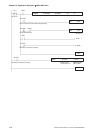
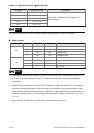
Relevant Parameters Description, cont.
Parameter
Communication
Address
Parameter Description
P2-45 022DH Combination Output Signal Delay Time [UNIT: 4msec]
Output signal will hold delay time when position command is
completed.
P2-46 022EH Feed Step Number
Range: 2~32
P2-47 022FH Position Deviation Clear Delay Time [UNIT: 20msec]
This function is disabled when its setting value is set to 0.
P2-51 0233H Internal Servo ON setting
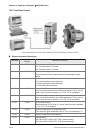
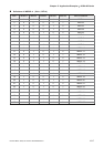
Digital I/O Signal Setting
DI Signal Parameter Setting Explanation
DI1 (INDEX0) P2-10 = 128 Feed step selection input 0
DI2 (INDEX1) P2-11 = 129 Feed step selection input 1
DI3 (INDEX2) P2-12 = 130 Feed step selection input 2
DI4 (INDEX3) P2-13 = 131 Feed step selection input 3
DI5 (ORGP) P2-14 = 124 Reference “Home” sensor
DI6 (SON) P2-15 = 101
Servo ON (when the setting value is 137, it is
manual operation function.)
(MDP0) P2-15 = 35 (contact “b”) Manually continuous operation
(MDP1) P2-15 = 36 (contact “b”) Manually single step operation
DI7 (MD0) P2-16 = 33 (contact “b”) Feed step mode input 0
DI8 (MD1) P2-17 = 34 (contact “b”) Feed step mode input 1