


Chapter 12 Application Examples|ASDA-AB Series
12-16 Revision March 2008, Doc. Name: 2007PDD23000011
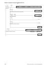
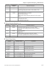
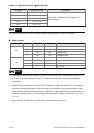
DO Signal Parameter Setting Explanation
DO1 P2-18 = 101
DO2 P2-19 = 103
DO3 P2-20 = 109
DO4 P2-21 = 105
DO5 P2-22 = 107
Please refer to “Definition of DO Signals” in the
following section.
NOTE
1) Please set parameter P2-08 to 12 before changing the setting value of DI and DO signals.
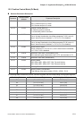
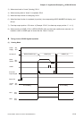
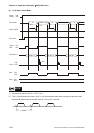
Mode Functions
MDP0, MDP1 Status MD1 MD0 Explanation
1 OFF OFF Torque decrease
2 OFF ON Feed step position mode
3 ON OFF Homing mode
OFF
4 ON ON Emergency stop
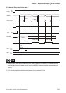
- - - Don’t care
- OFF ON CW manual operation
- ON OFF CCW manual operation
ON
- - - Don’t care
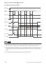
NOTE
1) The emergency stop warning message will appear if MD0 and MD1 are ON after power suppliers to AC
servo drive. If turn MD0 and MD1 to be OFF, the emergency stop warning message will disappear
automatically.
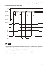
2) When the status is switched from 2 (MD1=OFF, MD0=ON) to 3 (MD1=ON, MD0=OFF), the emergency
stop warning message will appear. On the other hand, the emergency stop warning message will also
appear when the status is switched from 3 to 2. Therefore, no matter what status you want to switch to, it
is needed to switch to status 1 first to perform torque decrease (for example, switch from 2 Æ 1Æ 3 or 3
Æ 1 Æ 2).
3) Ensure that MD0 and MD1 are set to ON state to enforce an emergency stop.