Modbus TCP Remote I/O Communication Module RTU-EN01
DVP-PLC Operation Manual
11
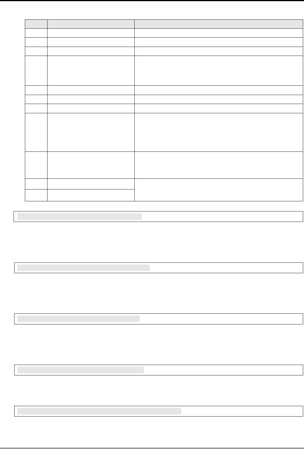
Code Indication How to correct
F0 Returning to default setting --
F1 RTU-EN01 being powered --
F2 Power supply in low voltage Check if the power supply of the module works normally.
F3 Internal error. Manufacturing error.
1. Check if the settings of smart PLC are incorrect.
2. Re-power RTU-EN01. If the error still exists, try step 3.
3. Reset RTU-EN01. If the error still exists, send the module back to
the manufacturer for repair.
F5 Network connection error Check if RTU-EN01 is connected normally to the network.
F6 Insufficient TCP connection Check if the number of connected modules exceeds the maximum.
F7 RS-485 setting error Check if the RS-485 communication format is correct.
F8 IP setting error
1. DHCP request failure.
2. IP setting error.
3. MASK setting error.
4. Gateway does not exist in the same subnet.
5. Returning to default setting.
F9 Right-side module error
Check if the configuration of the right-side module has been modified. If
the error still exists, check if the number of I/O points exceeds the
maximum and whether the there are more than 8 analog I/O modules
connected.
04 Slave error
0b No response from station
1. Check if RTU-EN01 and RS-485 is connected normally.
2. Check if the series transmission speed is consistent with that of other
nodes on the network.
BR#11: Communication Time-out (ms)
Explanations:
For setting up the communication time-out. Default = 5,000ms. For example, if you wish to set up the
communication time-out to 7 seconds manually, write 7000 to BR#11. Range: 5 ~ 65,535.
BR#12: Communication Delay Time (ms)
Explanations:
For setting up the minimum interval time between every Modbus command. Default = 0ms. For example, if you
wish to set up the communication delay time to 100ms manually, write 100 into BR#12. Range: 0 ~ 65,535.
BR#13: TCP Connection Idle Time (s)
Explanations:
For setting up the TCP connection idle time. Default = 30 seconds. For example, if you wish to set up the idle time
to 7 seconds manually, write 7 into BR#13. Range: 5 ~ 65,535.
BR#23: Number of Analog I/O Modules
Explanations:
Read the number of right-side modules from BR#23. Max. 8.
BR#24 ~ #31: ID of the 1
st
~ 8
th
Analog I/O Module
Explanations:
Read the ID of the 1
st
~ 8
th
analog I/O modules from BR#24 ~ BR#31.


