


Modbus TCP Remote I/O Communication Module RTU-EN01
DVP-PLC Operation Manual
15
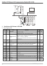
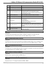
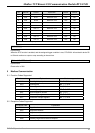
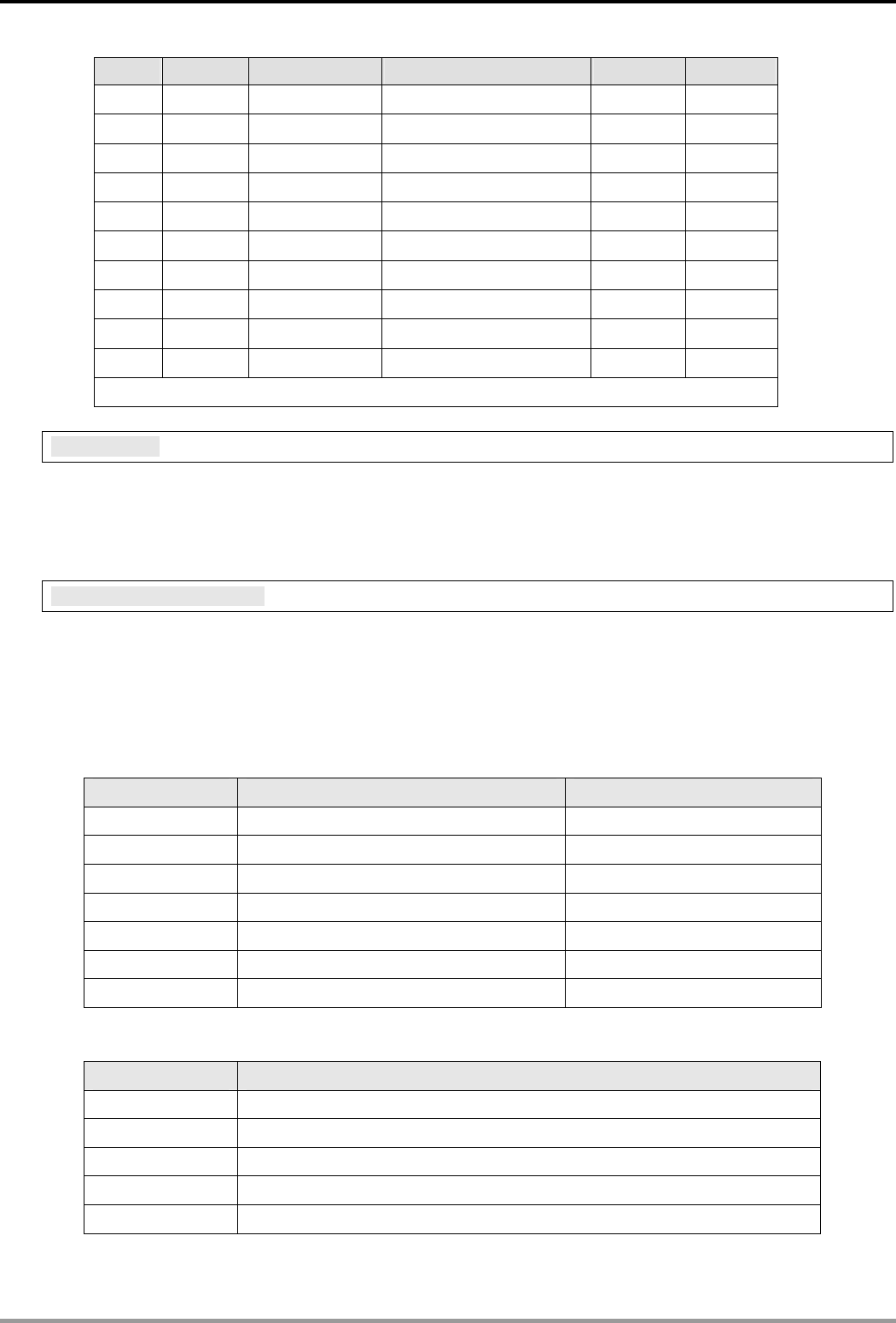
R# Attribute Content Explanation Default Latched
6 R/W RTC 6 Real-time clock OFF NO
7 R/W RTC 7 Real-time clock OFF NO
8 R/W RTC 8 Real-time clock OFF NO
9 R/W RTC 9 Real-time clock OFF NO
10 R/W RTC 10 Real-time clock OFF NO
11 R/W RTC 11 Real-time clock OFF NO
12 R/W RTC 12 Real-time clock OFF NO
13 R/W RTC 13 Real-time clock OFF NO
14 R/W RTC 14 Real-time clock OFF NO
15 R/W RTC 15 Real-time clock OFF NO
Symbol “R” refers to ready only; “R/W” refers to read and write.
R#0: RTC 0
Explanations:
When the RTC function is enabled, and the assigned trigger condition is true, RTU-EN01 will set the bit device R0
to ON and continue to output or stop according to the set time.
R#1 ~ #15: RTC 1 ~ 15
Explanations:
Please refer to R#0.
5 Modbus Communication
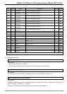
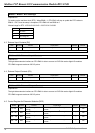
5.1 Function Codes Supported
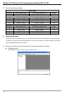
Function code Explanation Devices supported
0x02 Read digital input point RX, RY, T, R, C
0x03 Read register BR, T, C, RCR
0x05 Write single bit device RY, T, R, C
0x06 Write single register BR, T, C, RCR
0x0F Write multiple bit devices RY, T, R, C
0x10 Write multiple registers BR, T, C, RCR
0x17 Read/write multiple registers BR, T, C, RCR
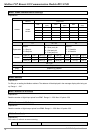
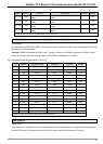
5.2 Exception Codes Supported
Exception code Explanation
0x01 Illegal function
0x02 Illegal data address
0x03 Illegal data value
0x04 Slave device failure
0x0b Gateway target device failed to respond.