


DS_DNM04SIP10_07162008D
12
FEATURE DESCRIPTIONS (CON.)
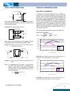
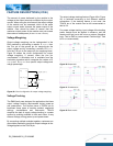
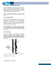
Sequential Start-up
Sequential start-up (Figure 40) is implemented by placing
an On/Off control circuit between Vo
PS1
and the On/Off pin
of PS2.
R1
R2
Vo
PS1
PS1
Vin
On/Off
On/Off
PS2
Vo
PS2
Vin
C1
Q1
R3
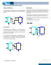
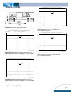
Simultaneous
Simultaneous tracking (Figure 41) is implemented by
using the TRACK pin. The objective is to minimize the
voltage difference between the power supply outputs
during power up and down.
The simultaneous tracking can be accomplished by
connecting Vo
PS1
to the TRACK pin of PS2. Please note
the voltage apply to TRACK pin needs to always higher
than the Vo
PS2
set point voltage.
TRACK
Vo
PS1
PS2
Vo
PS2
PS1
Vin
Vin
On/Off
On/Off
Ratio-Metric
Ratio–metric (Figure 42) is implemented by placing the
voltage divider on the TRACK pin that comprises R1 and
R2, to create a proportional voltage with Vo
PS1
to the Track
pin of PS2.
For Ratio-Metric applications that need the outputs of PS1
and PS2 reach the regulation set point at the same time.
The following equation can be used to calculate the value
of R1 and R2.
The suggested value of R2 is 10kΩ.
21
2
1,
2,
RR
R
V
V
PSO
PSO
+
=
R1
R2
TRACK
Vo
PS1
PS2
Vo
PS2
PS1
Vin
Vin
On/Off
On/Off
The high for positive logic
The low for negative logic