


DS_DNM04SIP10_07162008D
7
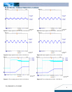
ELECTRICAL CHARACTERISTICS CURVES
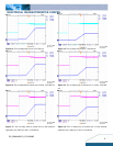
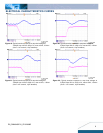
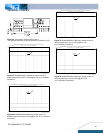
Figure 23: Typical transient response to step load change at
2.5A/μS from 100% to 50% of Io, max at 3.3Vin,
2.5Vout (Cout =1uF ceramic, 10μF tantalum)
Figure 24: Typical transient response to step load change at
2.5A/μS from 50% to 100% of Io, max at 3.3Vin,
2.5Vout (Cout =1uF ceramic, 10μF tantalum)
Figure 25: Typical transient response to step load change at
2.5A/μS from 100% to 50% of Io, max at 3.3Vin,
1.8Vout (Cout =1uF ceramic, 10μF tantalum)
Figure 26: Typical transient response to step load change at
2.5A/μS from 50% to 100% of Io, max at 3.3Vin,
1.8Vout (Cout = 1uF ceramic, 10μF tantalum)
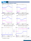
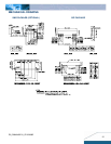
Figure 27: Output short circuit current 5Vin, 0.75Vout
Figure 28:Turn on with Prebias 5Vin, 3.3V/0A out, Vbias =1.0Vdc