


DS_DNM04SIP10_07162008D
14
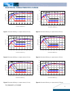
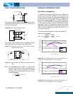
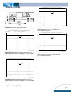
THERMAL CURVES
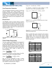
Figure 44: Temperature measurement location
* The allowed maximum hot spot temperature is defined at 125
℃
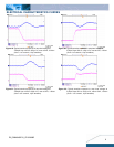
DNM04S0A0R10(Standard) Output Current vs. Ambient Temperature and Air Velocity
@ Vin = 5V, Vo = 3.3V (Either Orientation)
0
2
4
6
8
10
12
60 65 70 75 80 85
Ambient Temperature (
℃
)
Output Current(A)
Natural
Convection
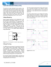
Figure 45: DNM04S0A0R10 (Standard) Output current vs.
ambient temperature and air velocity@Vin=5V, Vo=3.3V(Either
Orientation)
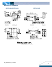
DNM04S0A0R10(Standard) Output Current vs. Ambient Temperature and Air Velocity
@ Vin = 5.0V, Vo = 0.75V (Either Orientation)
0
2
4
6
8
10
12
60 65 70 75 80 85
Ambient Temperature (
℃
)
Output Current(A)
Natural
Convection
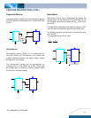
Figure 46: DNM04S0A0R10(Standard) Output current vs.
ambient temperature and air velocity@Vin=5V, Vo=0.75V(Either
Orientation)
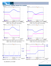
DNM04S0A0R10(Standard) Output Current vs. Ambient Temperature and Air Velocity
@ Vin = 3.3V, Vo = 2.5V (Either Orientation)
0
2
4
6
8
10
12
60 65 70 75 80 85
Ambient Temperature (
℃
)
Output Current(A)
Natural
Convection
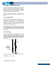
Figure 47: DNM04S0A0R10 (Standard) Output current vs.
ambient temperature and air velocity@Vin=3.3V,
Vo=2.5V(Either Orientation)
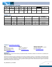
DNM04S0A0R10(Standard) Output Current vs. Ambient Temperature and Air Velocity
@ Vin = 3.3V, Vo = 0.75V (Either Orientation)
0
2
4
6
8
10
12
60 65 70 75 80 85
Ambient Temperature (
℃
)
Output Current(A)
Natural
Convection
Figure 48: DNM04S0A0R10 (Standard) Output current vs.
ambient temperature and air velocity@ Vin=3.3V,
Vo=0.75V(Either Orientation)