


Chapter 5 Parameters|VFD-S Series
5-66 Revision August 2008, SE09, SW V2.61
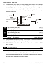
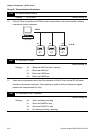
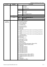
3.2 ADR (Communication Address)
Valid communication addresses are in the range of 0 to 254. A communication address
equal to 0, means broadcast to all AC drives (AMD). In this case, the AMD will not reply
any message to the master device.
00H: broadcast to all AC drives
01H: AC drive of address 01
0FH: AC drive of address 15
10H: AC drive of address 16
:
FEH: AC drive of address 254
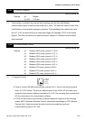
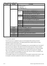
For example, communication to AMD with address 16 decimal (10H):
ASCII mode: Address=’1’,’0’ => ‘1’=31H, ‘0’=30H
RTU mode: Address=10H
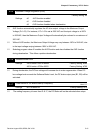
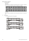
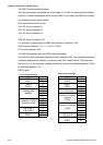
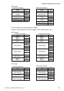
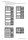
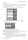
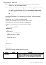
3.3 CMD (Command code) and DATA (data characters)
The format of data characters depends on the command code. The available command
codes are described as followed: Command code: 03H, read N words. The maximum
value of N is 12. For example, reading continuous 2 words from starting address 2102H
of AMD with address 01H.
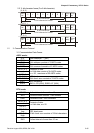
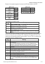
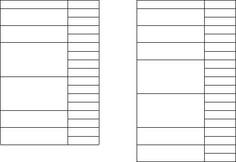
ASCII mode:
Command message:
Response message:
STX ‘:’ STX ‘:’
‘0’ ‘0’ ADR 1
ADR 0
‘1’
ADR 1
ADR 0
‘1’
‘0’ ‘0’ CMD 1
CMD 0
‘3’
CMD 1
CMD 0
‘3’
‘2’ ‘0’
‘1’
Number of data
(Count by byte)
‘4’
‘0’ ‘1’
Starting data
address
‘2’ ‘7’
‘0’ ‘7’
‘0’
Content of starting
address
2102H
‘0’
‘0’ ‘0’
Number of data
(count by word)
‘2’ ‘0’
‘D’ ‘0’ LRC CHK 1
LRC CHK 0
‘7’
Content of address
2103H
‘0’
CR ‘7’ END 1
END 0
LF
LRC CHK 1
LRC CHK 0
‘1’
CR
END 1
END 0
LF