


Appendix B Accessories|VFD-S Series
B-2 Revision August 2008, SE09, SW V2.61
7. Please read the wiring information in the user manual of the brake unit thoroughly prior to
installation and operation.
8. In applications with brake resistor or brake unit, Pr.6-00 (Over-voltage stall prevention)
must be disabled. And Pr.8-15 (AVR function) shall not be used.
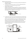
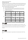
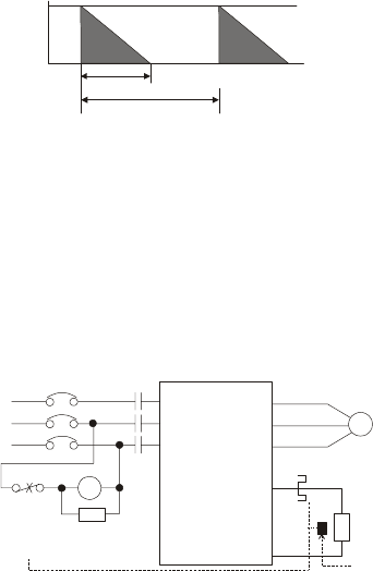
9. Definition for Brake Usage ED%
Explanation: The definition of the barke usage ED(%) is for assurance of enough time for
the brake unit and brake resistor to dissipate away heat generated by braking. When the
brake resistor heats up, the resistance would increase with temperature, and brake torque
would decrease accordingly. Suggest cycle time is one minute
100%
T0
T1
Brake Time
Cycle Time
ED% = T1/T0x100(%)
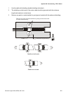
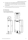
10. For safety reasons, install a thermal overload relay between brake unit and brake resistor.
Together with the magnetic contactor (MC) in the mains supply circuit to the drive it offers
protection in case of any malfunctioning. The purpose of installing the thermal overload
relay is to protect the brake resistor against damage due to frequent braking or in case
the brake unit is continuously on due to unusual high input voltage. Under these
circumstances the thermal overload relay switches off the power to the drive. Never let
the thermal overload relay switch off only the brake resistor as this will cause serious
damage to the AC Motor Drive.
R/L1
S/L2
T/L3
NFB
MC
VFD Series
MOTOR
O.L.
U/T1
V/T2
W/T3
SA
R/L1
S/L2
T/L3
MC
IM
Thermal
Overload
Relay or
temperature
switch
Surge
Absorber
B1
B2
BR
O.L.
Thermal Overload
Relay
Brake
Resistor
Tem per atu re
Switch