


Chapter 2 Installation and Wiring|VFD-S Series
2-26 Revision August 2008, SE09, SW V2.61
Terminal
Symbol
Terminal Function
Factory Settings (NPN mode)
ON: Connect to GND
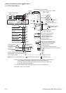
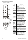
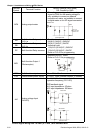
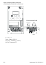
AFM Analog output meter
The voltage output type for this analog
signal is PWM, so this analog voltage is
only suitable to connect an external
movable coil meter, not suitable to connect
a digital meter or for A/D signal conversion.
Internal Circuit
AFM circuit
A
FM
GND
0~10V
Max. 2mA
ondometer
RA
Multi-function Relay output
(N.O.) a
RB
Multi-function Relay output
(N.C.) b
RC Multi-function Relay common
Resistive Load:
5A(N.O.)/3A(N.C.) 240VAC
5A(N.O.)/3A(N.C.) 24VDC
Inductive Load:
1.5A(N.O.)/0.5A(N.C.) 240VAC
1.5A(N.O.)/0.5A(N.C.) 24VDC
Refer to Pr.3-06 for programming
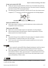
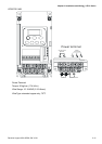
MO1
Multi-function Output 1
(Photocoupler)
Maximum 48VDC, 50mA
Refer to Pr.3-01 for programming
MO1-DCM
MO1
MCM
Max: 48Vdc
50mA
internal circuit
MCM Multi-function output common Max. 48Vdc 50mA
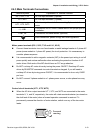
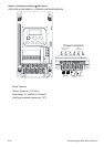
+10V Potentiometer power supply +10VDC 10mA (variable resistor: 3~5kohm)
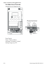
AVI
Analog voltage Input
(AVI/ACI)
0~+10V/4-20mA corresponds to 0-max.
operation frequency (Pr.01-00)
PID feedback signal
AVI input impedance: 47kohm
ACI input impedance: 250kohm
GND
A
VI
+10V
Internal Circuit
AVI circuit
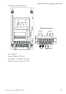
AVI
J1
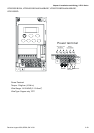
ACI
GND
A
CI
Internal Circuit
ACI circuit
AVI
J1
ACI
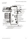
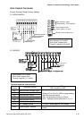
Control signal wiring size: 18 AWG (0.75 mm
2
) with shielded wire.