


Chapter 5 Parameters|VFD-S Series
Revision August 2008, SE09, SW V2.61 5-31
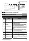
Group 3: Output Function Parameters
3-00
Analog Output Signal (AFM)
Factory Setting: d0
Settings d0 Analog Frequency Meter (0 to Maximum Output Frequency)
d1 Analog Current Meter (0 to 250% of rated AC motor drive current)
This parameter sets the function of the AFM output 0~+10VDC (ACM is common).
The voltage output type for this analog signal is PWM. It needs to read value by the movable
coil meter and is not suitable for A/D signal conversion.
3-01 Analog Output Gain Unit: 1
Settings d1 to d200% Factory Setting: d100
The parameter sets the voltage range of the analog output signal at terminals AFM, that
corresponds with either the output frequency or the output current of the VFD.
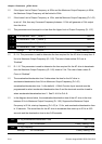
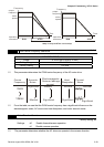
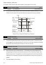
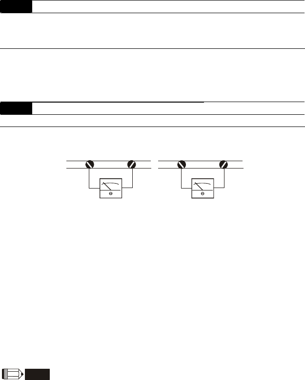
+-
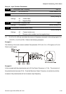
AFM
GND
Analog Frequency Meter
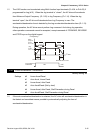
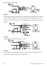
+-
AFM
GND
Analog Current Meter
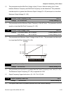
The analog output voltage is directly proportional to the output frequency of the AC drive. With
the factory setting of 100%, the Maximum Output Frequency (Pr.1-00) of the AC drive
corresponds to +10VDC analog voltage output. (The actual voltage is about +10VDC, and
can be adjusted by Pr.3-01).
The analog output voltage is directly proportional to the output current of the AC drive. With
the factory setting of 100%, the 2.5 times rated current of the AC drive corresponds to
+10VDC analog voltage output. (The actual voltage is about +10VDC, and can be adjusted by
Pr. 3-01)
The voltage output type of the output signal at terinals AFM is PWM, so this analog voltage is
only suitable to connect an external movable coil meter, not suitable to connect a digital meter
or for A/D signal conversion.
NOTE
Voltmeter specification: The sourcing capability of the output is limited to 0.21mA. Sourcing voltage:
10V. Output resistance: 47kΩ.
If the meter reads full scale at a voltage less than 10 volts, then Pr.3-01 should be set by the
following formula: Pr.3-01 = ((meter full scale voltage)/10) ×100%