


8
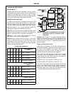
Operating Modes
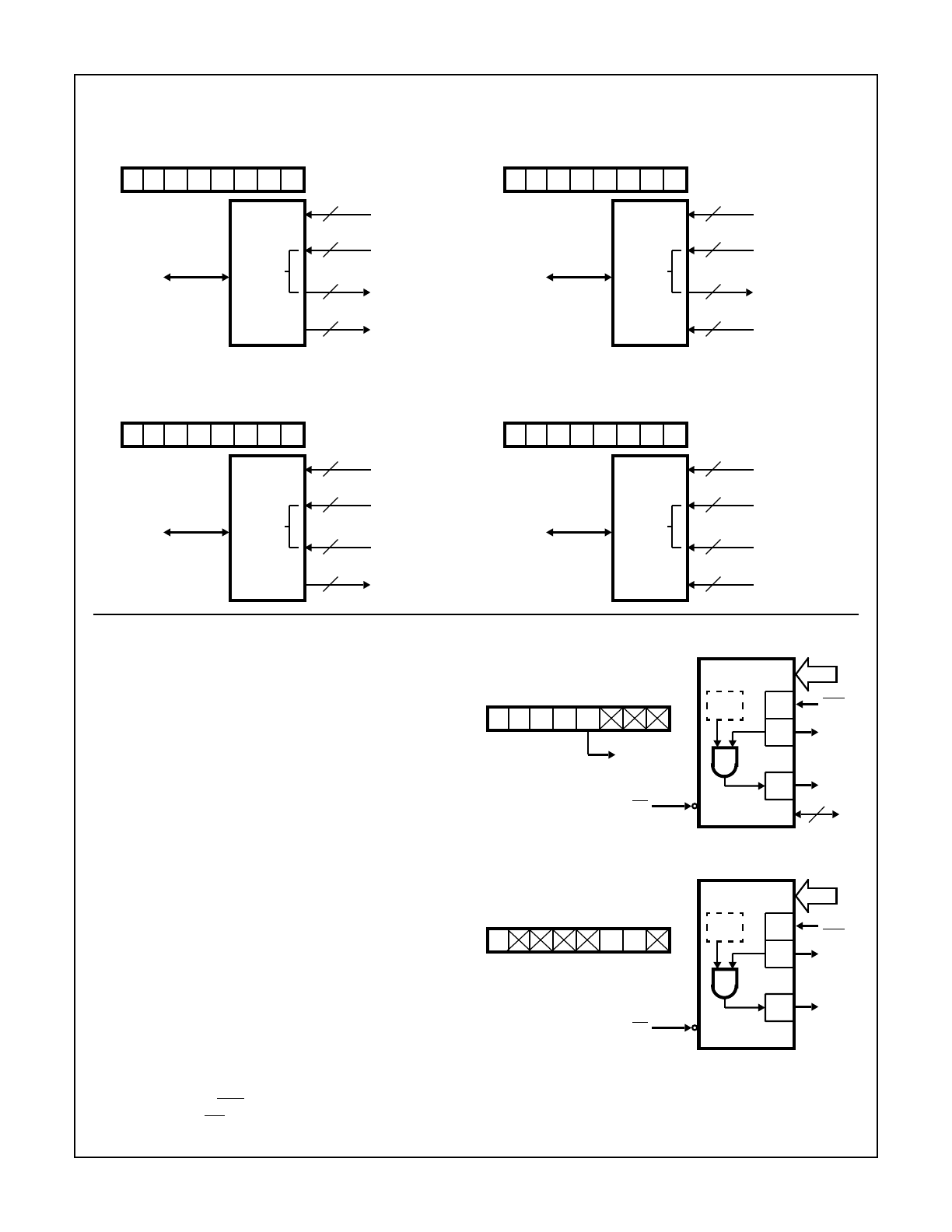
Mode 1 - (Strobed Input/Output). This functional configura-
tion provides a means for transferring I/O data to or from a
specified port in conjunction with strobes or “hand shaking”
signals. In mode 1, port A and port B use the lines on port C
to generate or accept these “hand shaking” signals.
Mode 1 Basic Function Definitions:
• Two Groups (Group A and Group B)
• Each group contains one 8-bit port and one 4-bit
control/data port
• The 8-bit data port can be either input or output. Both
inputs and outputs are latched.
• The 4-bit port is used for control and status of the 8-bit
port.
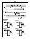
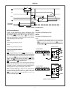
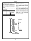
Input Control Signal Definition
(Figures 6 and 7)
STB (Strobe Input)
A “low” on this input loads data into the input latch.
IBF (Input Buffer Full F/F)
A “high” on this output indicates that the data has been
loaded into the input latch: in essence, and acknowledg-
ment. IBF is set by
STB input being low and is reset by the
rising edge of the
RD input.
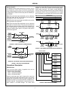
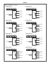
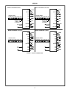
CONTROL WORD #12 CONTROL WORD #14
CONTROL WORD #13 CONTROL WORD #15
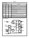
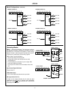
Mode 0 Configurations (Continued)
1
D7
0
D6
0
D5
1
D4
1
D3
0
D2
0
D1
0
D0
8
PA7 - PA0
4
PC7 - PC4
4
PC3 - PC0
8
PB7 - PB0
D7 - D0
82C55A
A
B
C
1
D7
0
D6
0
D5
1
D4
1
D3
0
D2
1
D1
0
D0
8
PA7 - PA0
4
PC7 - PC4
4
PC3 - PC0
8
PB7 - PB0
D7 - D0
82C55A
A
B
C
1
D7
0
D6
0
D5
1
D4
1
D3
0
D2
0
D1
1
D0
8
PA7 - PA0
4
PC7 - PC4
4
PC3 - PC0
8
PB7 - PB0
D7 - D0
82C55A
A
B
C
1
D7
0
D6
0
D5
1
D4
1
D3
0
D2
1
D1
1
D0
8
PA7 - PA0
4
PC7 - PC4
4
PC3 - PC0
8
PB7 - PB0
D7 - D0
82C55A
A
B
C
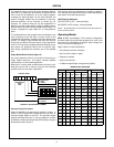
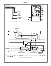
FIGURE 6. MODE 1 INPUT
1
D7
0
D6
1
D5
1
D4
1/0
D3
D2 D1 D0
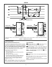
CONTROL WORD
MODE 1 (PORT A)
PC4
8
IBFAPC5
INTE
A
PA7-PA0
STBA
INTRA
PC3
PC6, PC7
I/O
2
RD
PC6, PC7
1 = INPUT
0 = OUTPUT
1
D7
D6 D5 D4 D3 D2 D1 D0
CONTROL WORD
MODE 1 (PORT B)
PC2
8
IBFBPC1
INTE
B
PB7-PB0
STBB
INTRB
PC0
RD
11
82C55A