


Chapter 2
MIL-3200X Series of FastPort Print Servers 2-3
I
N
S
T
A
L
L
A
T
I
O
N
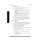
Table 2-1:
Operating Mode
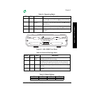
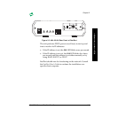
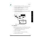
Figure 2-1. MIL-3200X Front Panel
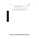
Table 2-2: Flash and Test Page Select
D3 D4 Mode Description
Up Up Normal Does not allow a Telnet session. Users can print to the
unit. The
SYS
(system) LED and
NET
(network) LED blink.
Down Up Telnet Diagnostic
Monitor
Allows a Telnet session to monitor FastPort or change its
parameters. Users can print to the unit. The
SYS
LED and
NET
LED blink.
Down Down Serial Diagnostic
Monitor
A terminal can be attached to serial port 2 to run a serial
monitor. Print jobs are not accepted. The
NET
LED blink.
Up Down Test Page A test page prints on a power cycle. No print jobs are
accepted.
Switch Position Mode Description
D1 Up Flash
Bank
Selects bank 0 (upper) to run the 4 Mb Flash EPROMs for
uploading the new firmware image.
Down Selects bank 1 (lower) to run the 4 Mb Flash EPROMs for
uploading. If the upgrade process fails, use this setting and
power cycle the unit to return FastPort to its default settings.
D2 Up Test Page MIL-3200X selects parallel port 2 and serial port 2 for test page
printing.
Down MIL-3200X selects parallel port 1 and serial port 1 for test page
printing.
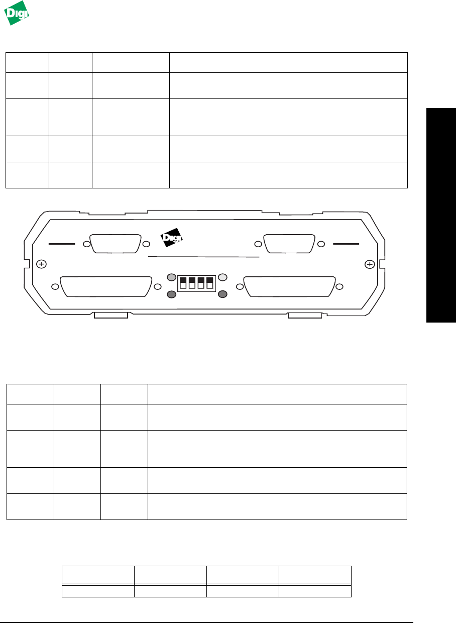
Table 2-3: Default Settings
D1 D2 D3 D4
Up Down Down Up
FASTPORT
4 PORT NETWORK PRINT SERVER
MODEL MIL•3200X
1 2 3 4
12
SERIAL
SERIAL
PARALLEL
PARALLEL
S1 S2
P1P2
TM