


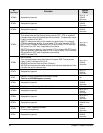
34 Chapter 9 Modem Emulation
application if the remote side closes the TCP connection.
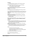
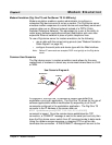
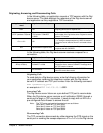
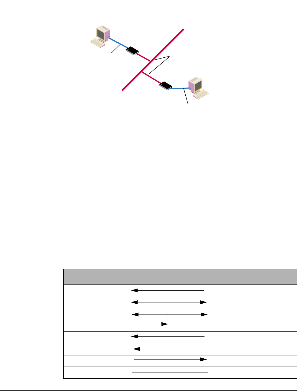
In Diagram B, two Digi device servers will replace modems on both sides of
the connection. The initiation of the connection occurs with either of the
Digi device servers. If both ends are Digi device servers, the TCP listening
port number is 50001 for port 1. An example of the connection command is
ATDT 192.168.25.30:50001. Upon establishing a successful TCP
connection, a CONNECT message is sent to the serial port and only then
does the Digi device server switch from AT command mode to data mode.
After the CONNECT is received, the transmission of data begins. Using
the modem escape sequence or dropping DTR on either side terminates
the connection.
Modem emulation has the ability to communicate to an infinite number of
other devices.
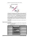
Modem Emulation Cable Signals
Use the following signal assignments to make a cable connecting the Digi
device server to a serial device.
Note: DSR and DTR on the serial device side are connected to the DSR signal of
the Digi device server.
D
I
G
I
O
N
E
T
S
D
I
G
I
O
N
E
T
S
192.168.25.30
Workstation
Digi One TS
#1
Digi One TS
#2
Ethernet
Serial cable
User Scenario-Diagram B
Serial cable
Workstation
Serial Device Digi Device Server
CTS (in) RTS (out)
RTS (out) CTS (in)
DSR (in) DSR (in)
DTR (out)
DCD (in) DTR (out)
TX (out) RX (in)
RX (in) TX (out)
GND GND