


11
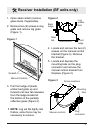
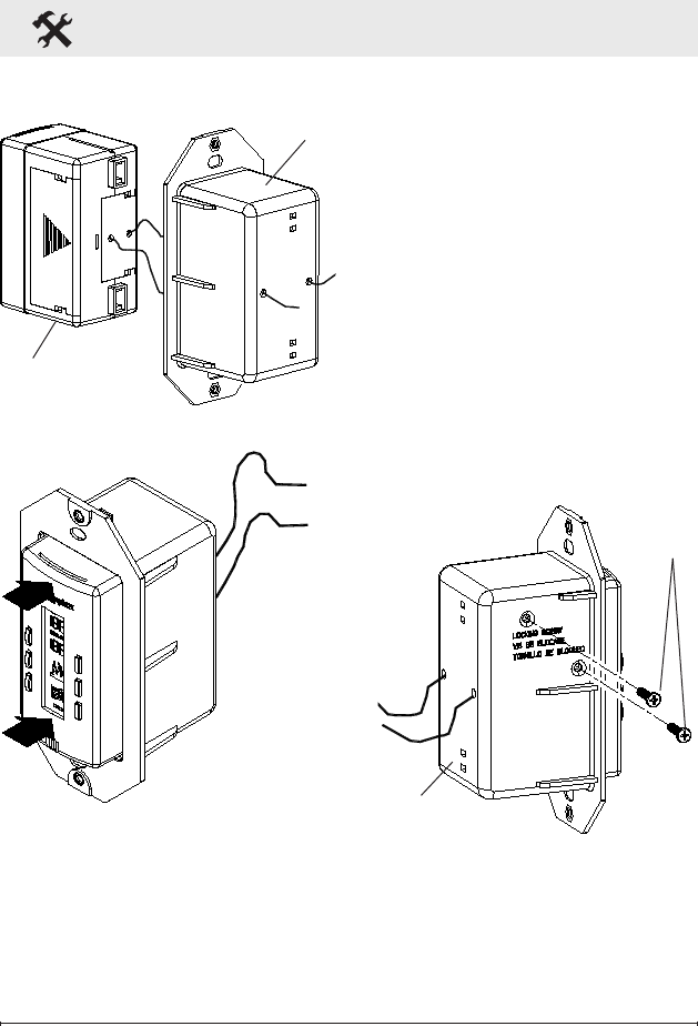
Wall Control Installation
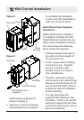
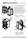
Figure 12
Controller
Outer
Housing
Figure 13
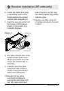
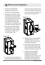
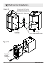
Locking Screw Option (Figure 14)
To prevent tampering, damage,
and theft, it is suggested to
install the locking screws. Once
installed, the locking screws will
prevent the Controller from being
released from the Outer Housing
without being removed rst from
the device box in the wall.
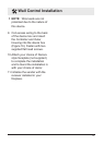
!
NOTE: A Philips head
screwdriver will be required for
this step.
8. Using the wiring diagram
in Figure 15 as a guide,
make the appropriate wire
connections.
Figure 14
Locking
screws
Outer
Housing