© 2004 Directed Electronics, Inc
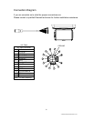
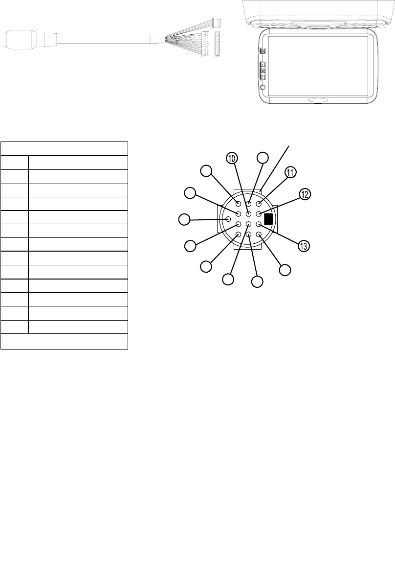
Connection Diagram
If you are uncertain as to what the proper connections are.
Please contact a qualified Directed technician for further installation assistance.
1
6
4
8
2
7
5
9
3
GROUND
A
/V Cable
A/V Input Connector
Pin
1
2
3
4
5
6
7
8
9
10
11
12
GND A/V GND Shielding
Function
Audio B-L
IR EXT
Audio B-R
Audio A-L
ACC
Audio A-R
MUTE
Video 2
GND
Source select B
12V
Source select A
18


