


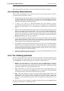

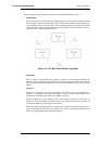

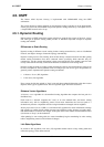
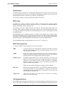
Figure 4.7. A Route Load Balancing Scenario
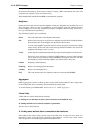
We first need to define two routes to these two ISPs in the main routing table as shown below:
Route No. Interface Destination Gateway Metric
1 WAN1 all-nets GW1 100
2 WAN2 all-nets GW2 100
We will not use the spillover algorithm in this example so the routing metric for both routes should
be the same, in this case a value of 100 is selected.
By using the Destination RLB algorithm we can ensure that clients communicate with a particular
server using the same route and therefore the same source IP address. If NAT was being used for the
client communication, the IP address seen by the server would be WAN1 or WAN2.
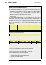
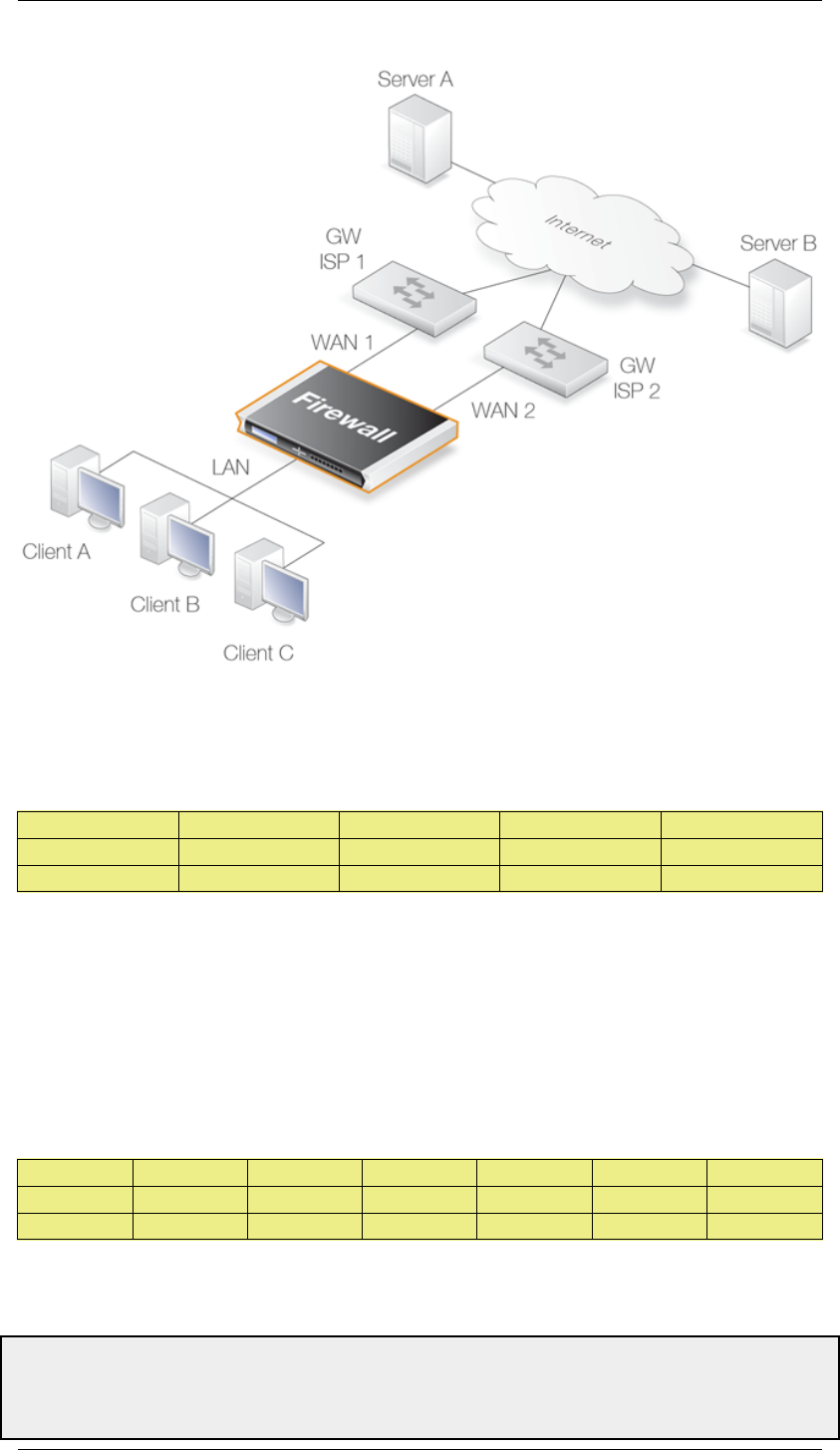
In order to flow, any traffic requires both a route and an allowing IP rule. The following rules will
allow traffic to flow to either ISP and will NAT the traffic using the external IP addresses of
interfaces WAN1 and WAN2.
Rule No. Action Src Interface Src Network Dest Interace Dest Network Service
1 NAT lan lannet WAN1 all-nets All
1 NAT lan lannet WAN2 all-nets All
The service All is used in the above IP rules but this should be further refined to a service or service
group that covers all the traffic that will be allowed to flow.
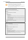
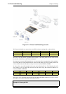
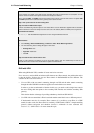
Example 4.6. Setting Up RLB
4.4. Route Load Balancing Chapter 4. Routing
169