


Rule
Name
Forward
Pipes
Return
Pipes
Source
Interface
Source
Network
Dest
Interface
Dest
Network
Selected
Service
Prece
dence
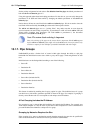
voip out-pipe in-pipe lan lannet wan all-nets H323 6
citrix out-pipe in-pipe lan lannet wan all-nets citrix 4
other out-pipe in-pipe lan lannet wan all-nets All 2
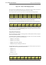
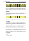
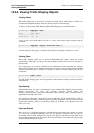
These rules are processed from top to bottom and force different kinds of traffic into precedences
based on the Service. Customized service objects may need to be first created in order to identify
particular types of traffic. The all service at the end, catches anything that falls through from earlier
rules since it is important that no traffic bypasses the pipe rule set otherwise using pipes will not
work.
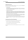
Pipe Chaining
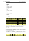
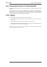
Suppose the requirement now is to limit the precedence 2 capacity (other traffic) to 1000 kbps so
that it does not spill over into precedence 0. This is done with pipe chaining where we create new
pipes called in-other and out-other both with a Pipe Limit of 1000. The other pipe rule is then
modified to use these:
Rule
Name
Forward
Pipes
Return
Pipes
Source
Interface
Source
Network
Dest
Interface
Dest
Network
Selected
Service
Prece
dence
other out-other
out-pipe
in-other
in-pipe
lan lannet wan all-nets All 2
Note that in-other and out-other are first in the pipe chain in both directions. This is because we
want to limit the traffic immediately, before it enters the in-pipe and out-pipe and competes with
VoIP, Citrix and Web-surfing traffic.
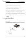
A VPN Scenario
In the cases discussed so far, all traffic shaping is occurring inside a single NetDefend Firewall.
VPN is typically used for communication between a headquarters and branch offices in which case
pipes can control traffic flow in both directions. With VPN it is the tunnel which is the source and
destination interface for the pipe rules.
An important consideration which has been discussed previously, is allowance in the Pipe Total
values for the overhead used by VPN protocols. As a rule of thumb, a pipe total of 1700 bps is
reasonable for a VPN tunnel where the underlying physical connection capacity is 2 Mbps.
It is also important to remember to insert into the pipe all non-VPN traffic using the same physical
link.
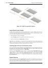
The pipe chaining can be used as a solution to the problem of VPN overhead. A limit which allows
for this overhead is placed on the VPN tunnel traffic and non-VPN traffic is inserted into a pipe that
matches the speed of the physical link.
To do this we first create separate pipes for the outgoing traffic and the incoming traffic. VoIP
traffic will be sent over a VPN tunnel that will have a high priority. All other traffic will be sent at
the best effort priority (see above for an explanation of this term). Again, we will assume a 2/2
Mbps symmetric link.
The pipes required will be:
• vpn-in
• Priority 6: VoIP 500 kpbs
• Priority 0: Best effort
10.1.10. More Pipe Examples Chapter 10. Traffic Management
462