


10/100 Fast Ethernet Switch User’s Guide
Identifying External Components
15
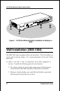
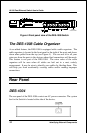
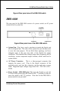
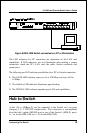
Figure 5 Rear panel view of the DES-1004 switch
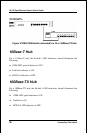
DES-1008
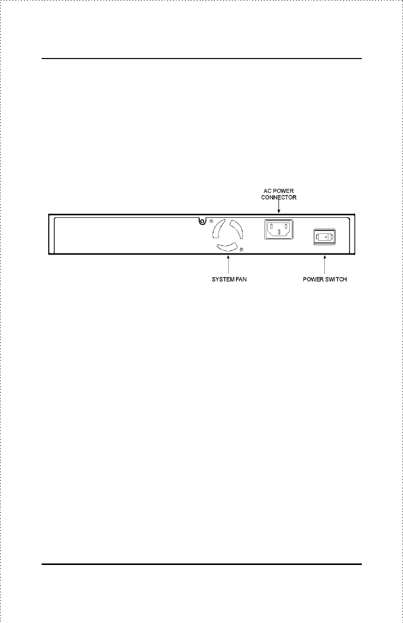
The rear panel of the DES-1008 consists of a power switch, an AC power
connector and a system fan.
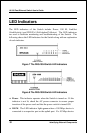
Figure 6 Rear panel view of the DES-1008 switch
♦ System Fan. This fan is used to circulate air inside the Switch and
also to dissipate heat. The sides of the system also provide heat vents
to serve the same purpose. Do not block these openings, and leave
adequate space at the rear and sides of the Switch for proper
ventilation. Be reminded that without proper heat dissipation and air
circulation, system components might overheat, which could lead to
system failure.
♦ AC Power Connector. This is a three-pronged connector that
supports the power cord. Plug in the female connector of the
provided power cord into this connector, and the male into a power
outlet. Supported input voltages range from 100 ~ 240 VAC at 50 ~
60 Hz.
♦ Power Switch. (DES-1008 only) This turns the Switch on and off.
To turn on the system, press the switch to the “1” position; to turn off,
press the switch to the “0” position. Note that on the DES-1004 a
power switch is not provided.