


DGS-3000 Series Layer 2 Managed Gigabit Switch Hardware Installation Guide
12
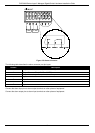
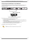
Figure 2-5 Alarm Connector
The following table describes the alarm connector port pin layout.
Contact Description
1
Output. Normal Closed Pin. (42VAC or 60VDC)
2
Output. Common Pin. (42VAC or 60VDC)
3
Output. Normal Open Pin. (42VAC or 60VDC)
4
Input 2
5
Input 2
6
Input 1
7
Input 1
Connect the alarm input pins to alarm output terminals on other pieces of equipment.
Connect the alarm output pins to alarm input terminals on other pieces of equipment.