


DGS-3000 Series Layer 2 Managed Gigabit Switch Hardware Installation Guide
37
Appendix B – Cables and Connectors
Ethernet Cable
When connecting the Switch to another switch, a bridge or hub, a normal cable is necessary. Please review these
products for matching cable pin assignment.
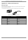
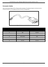
The following diagrams and tables show the standard RJ-45 receptacle/connector and their pin assignments.
Figure B- 1. The standard RJ-45 port and connector
RJ-45 Pin Assignments
Contact MDI-X Port MDI-II Port
1
RD+ (receive) TD+ (transmit)
2
RD- (receive) TD- (transmit)
3
TD+ (transmit) RD+ (receive)
4
1000BASE-T 1000BASE-T
5
1000BASE-T 1000BASE-T
6
TD- (transmit) RD- (receive)
7
1000BASE-T 1000BASE-T
8
1000BASE-T 1000BASE-T