


xStack
®
DGS-3400 Series Layer 2 Gigabit Ethernet Managed Switch
6
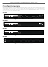
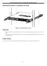
Rear Panel Description
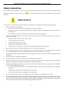
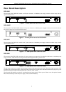
DGS-3426
The rear panel of the DGS-3426 contains an AC power connector, a redundant power supply connector and two empty slots for
optional module inserts.
Figure 1 - 9 Rear panel view of the DGS-3426
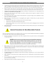
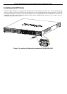
DGS-3426P
The rear panel of the DGS-3426P contains an AC power connector, a redundant power supply connector, a heat vent for the rear
fan and two empty slots for optional module inserts.
Figure 1 - 10 Rear panel view of the DGS-3426P
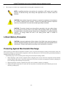
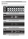
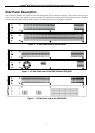
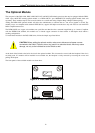
DGS-3427
The rear panel of the DGS-3427 contains an AC power connector, a redundant power supply connector and three empty slots for
optional module inserts.
Figure 1 - 11 Rear panel view of the DGS-3427
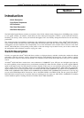
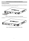
DGS-3450
The rear panel of the DGS-3450 contains an AC power connector, two empty slots for optional module inserts, a redundant power
supply connector, a RS-232 DCE console port for Switch management and a system fan vent.
Figure 1 - 12 Rear panel view of the DGS-3450
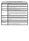
The AC power connector is a standard three-pronged connector that supports the power cord. Plug-in the female connector of the
provided power cord into this socket, and the male side of the cord into a power outlet. The Switch automatically adjusts its power
setting to any supply voltage in the range from 100 ~ 240 VAC at 50 ~ 60 Hz.
The rear panel also includes an outlet for an optional external power supply. When a power failure occurs, the optional external
RPS will automatically assume the power supply for the Switch immediately.