


xStack
®
DGS-3400 Series Layer 2 Gigabit Ethernet Managed Switch
12
The Optional Module
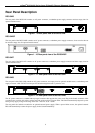
The rear panel of the DGS-3426, DGS-3426P, DGS-3427 and DGS-3450 include open slots that may be equipped with the DEM-
410X 1-port 10GE XFP stacking uplink module, or a DEM-410CX 1-port 10GBASE-CX4 stacking uplink module, both sold
separately. These modules may be used to stack switches in a switch stack using a Duplex Ring or Duplex Chain topology.
Adding the DEM-410X optional module will allow the administrator to transmit data at a rate of ten gigabits a second. The
module port(s) are compliant with standard IEEE 802.3ae, support full-duplex transmissions only and must be used with XFP
MSA compliant transceivers.
The DEM-410CX uses copper wire medium, not optic fiber and therefore has a transmit length limit up to 1 meter. Compliant
with the IEEE802.3ak standard, this module uses a 4-laned copper connector for data transfer in full-duplex mode within a
stacking configuration.
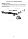
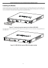
To install these modules in the DGS-3400 Series, follow the simple steps listed below.
CAUTION: Before adding the optional module, make sure to disconnect all power sources
connected to the Switch. Failure to do so may result in an electrical shock, which may cause
damage, not only to the individual but to the Switch as well.
At the back of the Switch to the left is the slot for the optional module. This slot must be covered with the faceplate if the slot is
not being used. If a module will be installed in an available slot, the faceplate is easily removed by loosening the screws and
pulling off the plate.
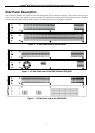
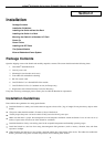
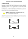
The front panels of the available modules are shown here:
Figure 2- 5. Front Panel of the DEM-410X
Figure 2- 6. Front Panel of the DEM-410CX